4
SPECIFICATIONS
Table 3—Cooling Only
COOLING ONL Y
System
Size 18 24 30 34 34 34
Outdoor Model
24AH A 418A 003
124AN S018000
24AH A 424A 003
124AN S024000
24AH A 430A 003
124AN S030000
24AH A 436A 003
124AN S036000
24AH A 436A 005
124APS 036000
24AH A 436A 006
124AE S 036000
Indoor M odel 40MK CB 18C----3 40MK CB 34C----3 40MK CB 34C----3 40MK CB 34C----3 40MK CB 34C----3 40MK CB 34C----3
Energy Star NO NO NO NO NO NO
Performance
Cooling Rated Capacity Btu/h 17,100 23,800 30,000 34,200 34,200 34,200
SEER 14 14 14 14 14 14
EER 12.2 12.2 12.2 12.2 12.2 12.2
Controls
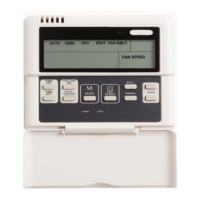
Wire less Remote Controller (_F/_C Conver t i bl e ) Sta ndard Standar d St a nda rd Standa rd Standa rd Standard
W i r ed Remot e Controll e r (_F/_C Converti bl e ) Opti ona l Opti ona l Optional Opti onal Opti onal Opt ional
Operating
Range
Cooli ng Outdoor D B Min -- Ma x _F
55~125 (--2
0Fw/
Low--Ambient Kit)
55~125 (--2
0Fw/
Low--Ambient Kit)
55~125 (--2
0Fw/
Low--Ambient Kit)
55~125 (--2
0Fw/
Low--Ambient Kit)
55~125 (--2
0Fw/
Low--Ambient Kit)
55~125 (--2
0Fw/
Low--Ambient Kit)
Cooli ng Indoor DB Min --Max _F 64~90 64~90 64~90 64~90 64~90 64~90
Piping
Total Piping Length** Ft. 200’ 200’ 200’ 200’ 200’ 200’
Dr op (O D a bove I D ) Ft. 200’ 200’ 200’ 200’ 200’ 200’
Lift (OD below ID) Ft. 65’ 65’ 65’ 65’ 65’ 65’
Outdoor P i pe Conne c t i on Siz e -- Liquid* In. 3/8” 3/8” 3/8” 3/8” 3/8” 3/8”
Outdoor P i pe Conne c t i on Siz e -- Suction In. 5/8” 3/4” 3/4” 7/8” 7/8” 7/8”
Indoor P i pe Connection Siz e -- Liquid In. 3/8” 3/8” 3/8” 3/8” 3/8” 3/8”
Indoor P i pe Connection Siz e -- Sucti on In. 5/8” 3/4” 3/4” 3/4” 3/4” 3/4”
Refrigerant
Type R--410A R--410A R--410A R--410A R--410A R--410A
Design Pressure PSIG 550 550 550 550 550 550
Me t e ring Devi c e Type B Ac c urator Type B Ac c urator Type B Ac c urator Type B Ac c urator Type B Ac c urator Type B Ac c urator
Charge Lb. 6.4 6.5 8.6 8.9 8.9 8.9
Ou tdoor
Coil
Face Area Sq. Ft. 7.3 7.3 12.1 12.1 12.1 12.1
No. Rows 2 2 2 2 2 2
Fins per inch 20 20 20 20 20 20
Circuits 3 3 3 3 3 3
Indoor
Coil
Face Area (sq. ft.) Sq. Ft. 3.6 5.6 5.6 5.6 5.6 5.6
No. Rows 2 3 3 3 3 3
Fins per inch 18 18 18 18 18 18
Circuits 8 12 12 12 12 12
Compressor
Type Scroll Scroll Scroll Scroll Scroll Scroll
Mode l Z P 16K 6E--PFV--130 ZP 20K 6E--PFV--130 ZP 25K 5E--PFV--130 ZP 29K 5E--PFV--130 ZP 29K 5E--TF5--130 ZP29K 5E--TF D--130
Electrical
Outdoor Voltage , Pha s e , Cyc l e
V/Ph/
Hz
208/230--1--60 208/230--1--60 208/230--1--60 208/230--1--60 208/230--3--60 460--3--60
Indoor Volt a ge , P ha se, Cycle
V/Ph/
Hz
208/230--1--60 208/230--1--60 208/230--1--60 208/230--1--60 208/230--1--60 208/230--1--60
Power Supply
Indoor a nd outdoor
units have dedi cat e d
powe r suppl y
Indoor a nd outdoor
units have dedi cat e d
powe r suppl y
Indoor a nd outdoor
units have dedi cat e d
powe r suppl y
Indoor a nd outdoor
units have dedi cat e d
powe r suppl y
Indoor a nd outdoor
units have dedi cat e d
powe r suppl y
Indoor a nd outdoor
units have dedi cat e d
powe r suppl y
MCA ( O ut door) A. 11.8 14.1 18.3 18.8 12.5 7.6
MO CP -- Fuse Rating (O ut door) A. 20 25 30 30 20 15
MCA ( Indoor) A. 1 1 1 1 1 1
MO CP -- Fuse Rating (Indoor) A. 15 15 15 15 15 15
Ou tdoor
Unit Width In. 36.9 36.9 44.5 44.5 44.5 44.5
Unit Height In. 31.1 31.1 37.1 37.1 37.1 37.1
Unit Depth In. 14.6 14.6 17.1 17.1 17.1 17.1
Ne t Weight Lbs. 146 148 183 184 184 184
Airflow CFM 1,285 1,285 1,900 2,615 2,615 2,615
Indoor
Unit Width Body In. 33.1 33.1 33.1 33.1 33.1 33.1
Unit H e i ght Body In. 33.1 33.1 33.1 33.1 33.1 33.1
Unit D e pt h Body In. 11.3 11.3 11.3 11.3 11.3 11.3
Ne t Weight Body Lbs. 54.0 68.6 68.6 68.6 68.6 68.6
Unit Width Grille In. 37.4 37.4 37.4 37.4 37.4 37.4
Unit Height Grille In. 37.4 37.4 37.4 37.4 37.4 37.4
Unit Depth Grille In. 2.2 2.2 2.2 2.2 2.2 2.2
Net Weight Grille Lbs. 11.0 11.0 11.0 11.0 11.0 11.0
Number of Fan Speeds 3 3 3 3 3 3
Airf l ow (l owest to highes t ) CFM 370/450/630 750/820/1130 750/820/ 1130 750/820/1130 750/820/1130 750/820/1 130
Sound Pre ss ure (lowest to highes t) dB(A) 39/43/ 47 44/48/53 44/48/53 44/48/53 44/48/53 44/48/53
Air t hrow Dat a Ft. 15 16 16 16 16 16
* Liquid line needs to be insulated
** Refer to Ductless Split System Long Line Guide for additional information. Long Line accessories required beyond 80 ft (24.4 m).
 Loading...