4
Brazi ng Connections
Connect vapor tube to fitting on outdoor unit vapor service valves
(see Table 2). Connect liquid tubing to adapter tube on liquid
service valve. Use refrigerant grade tubing.
!
UNIT DAMAGE HAZARD
Failure to follow this caution may result in equipment
damage or improper operation.
Service valves must be wrapped in a heat–sinking material
such as a wet cloth while brazing.
CAUTION
Apply heat absorbing paste or heat sink product between service
valve and joint. Wrap service valves with a heat sinking material
such as a wet cloth.
After wrapping service valve with a wet cloth, tubing set can be
brazed to service valve using either silver bearing or non–silver
bearing brazing material. Do not use soft solder (materials which
melt below 800°F/427°C). Consult local code requirements.
NOTE: Some outdoor units contain a mechanical fitting at the
liquid distributor. This connection is not field serviceable and
should not be disturbed.
NOTE: For Liquid Service Valve -- Braze lineset to adapter tube
BEFORE bolting adapter to valve. This helps prevent overheating
and damage to plastic washer or o--ring.
For Vapor Service Valve -- remove valve core from schrader port
on Service Valve BEFORE brazing. This helps prevent
overheating and damage to valve seals (refer to Fig. 5). Replace
valve c or e when bra zing is comple te d.
VALVE CORE
SERVICE VALVE
A14236
Fig. 5 --- VaporServiceValve
FIRE HAZARD
Failure to following this warning could result in personal
injury, death and/or property damage.
Refrigerant and oil mixture could ignite and burn as it escapes
and contacts brazing torch. Make sure the refrigerant charge is
properly removed from both the high and low sides of the
system before brazing any component or lines.
!
WARNING
Clean line set tube ends with emery cloth or steel brush. Remove
any grit or debris.
Insert line set tube ends into service valve tube stubs.
Apply heat absorbing paste or heat sink product between service
valve and joint. Wrap service valves with a heat sinking material
such as a wet cloth.
Braze joints using a Sil--Fos or Phos-- copper alloy.
Table 2—Refrigerant Connections and Recommended Liquid
and Vapor Tube Diameters (In.)
UNIT SIZE
LIQUID RATED VAPOR
Connection
Diameter
Tube
Diameter
Connection
Diameter
Tube
Diameter
18, 24 3/8 3/8 5/8 5/8
30, 36 3/8 3/8 3/4 3/4
42, 48 3/8 3/8 7/8 7/8
60 3/8 3/8 7/8 1–1/8
* Units are rated with 25 ft. (7.6 m) of lineset. See Product Data sheet for performance
data when using different size and length linesets.
Notes:
1. Do not apply capilla ry tube indoor coi l s to these units.
2. For Tubing Set lengths between 80 and 200 ft. (24.38 and 60.96 m) horizontal or
20 ft. (6.09 m) vertical differential 250 ft. (76.2 m) To tal Equivalent Length, refer to
the Residential Piping and Longline Guideline – Air Conditioners and Heat Pumps
using Puron refrigerant.
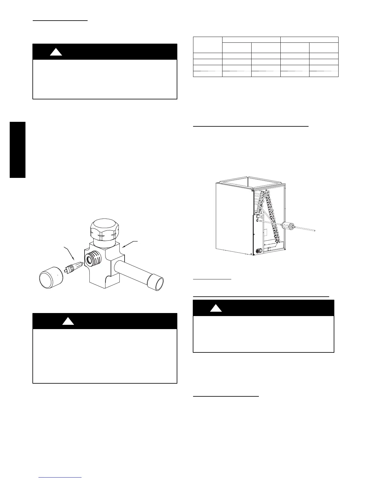
Install Liquid Line Filter Drier Indoor
Refer to Fig. 6 and install filter drier as follows:
1. Braze 5 in. (127 mm) liquid tube to the indoor coil.
2. Wrap filter drier with damp cloth.
3. Braze filter drier to 5 in. (127 mm) long liquid tube from
step 1.
4. Connect and braze liquid refrigerant tube to the filter drier.
A05227
Fig. 6 --- Liquid Line Filter Drier
Leak Testing
Leak test all joints; indoors, outdoors, and refrigerant tubing.
Evacuate Refrigerant Tubing and Indoor Coil
CAUTION
!
UNIT DAMAGE HAZARD
Failure to follow this caution may result in equipment
damage or improper operation.
Never use the system compressor as a vacuum pump.
Refrigerant tubes and indoor coil should be evacu ated using the
recommended deep vacuum method of 500 microns. An alternate
triple evacuation method may also be used. See Service Manual
for Triple Evacuation Method.
IMPORTANT: Always break a vacuum with dry nitrogen.
Deep Vacuum Method
The deep vacuum method requires a vacuum pump capable of
pulling a vacuum of 500 microns and a vacuum gage capable of
accurately measuring this vacuum depth. The deep vacuum method
is the most positive way of assuring a system is free of air and
liquidwater.(SeeFig.7.)
25HNB5
 Loading...