17
English
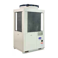
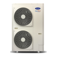
For dimensions see g. 1
30AWH A B C D E F G H L
kg
004_ 1Ph 908 821 326 350 87 356 466 40 60 57
006_ 1Ph 908 821 326 350 87 356 466 40 60 61
008_ 1Ph 908 821 326 350 87 356 466 40 60 69
012_1Ph 908 1363 326 350 174 640 750 44 69 104
015_1Ph 908 1363 326 350 174 640 750 44 69 112
012_3Ph 908 1363 326 350 174 640 750 44 69 116
015_3Ph 908 1363 326 350 174 640 750 44 69 116
Minimuminstallationclearancesinmmareshowning.2(singleinstallation)andg.3(serialinstallation)
NOTE: The height of the obstacle at both front and rear side should be lower than the height of the outdoor unit.
Unit
30AWH
004H 006H 008H 012H 015H 004X 006X 008X 012X 015X
Compressor Type Rotary DC Inverter Tecnology
Water pump speed Variable speed N.A.
Expansion vessel
Capacity l 2 3 N.A.
Nitrogen precharge pressure kPa 200 N.A.
Net water volume l 1 1 1.2 2.5 2.5 0.8 0.8 1 2.3 2.3
Water connections 1''M
Maximum water pressure kPa 300
Before installation, check strength and horizontality of the
base so that abnormal sound does not generate.
According to the dimensions and clearances, x the base
rmly with the anchor bolts (Anchor bolt, nut: M10 x 2
pairs).
If the outdoor unit is installed in a very windy place,
protect the fan with a wind protection screen and check
that it works correctly.
5.1 - Opening cable knockouts (Fig. 4)
There is a pre-cut part that can be removed for running
wires.
Do not remove the unit front panel for easier drilling of
the knockouts. The pre-cut section of the sheet can be
removed by punching the 3 connection points along the
line rst using a chisel and nally with pliers (see g. 4).
When the cable knockout is open, remove the burrs and t
the cable protective bush supplied with the unit for cable
protection.
1. Remove screws of the front panel (See g 5).
2. Pull the front panel downward with the handle.
5.3 - Drain hose and base pan knockouts (Fig. 6)
See g. 6.
In case of draining through the drain hose, attach the drain
nipple (A) and use the drain hose (Inner diam.: 16mm)
sold in the market. When there is a possibility of freezing
of drain at the cold district or a snowfall area, be careful
for drainage ability of drain.
The drainage ability increases when knockout holes on the
base pan are opened. (Open the knockout hole to outside
using a soft-faced hammer (B), etc.).
Operation in cooling: See g. 7
NOTE: For the 30AWH004_ and 30AWH006_ units use
a minimum External Air Temperature of +5 °C.
(- -30AWH006_ ,- . -30AWH004_ )
Operation in heating: See g. 8
 Loading...