24
English
30AWH__X
Description PIN Signal Limits
33AW-CS1B Installation
Menu Code
Additional external temperature probe 23 - 24 Input(NTC3kΩ@25°C) N.A. 126
Sanitary Water Request 13 - 15 Input(contactswitchquality>25mA@12V) N.A. 153
Maximum Frequency Reduction Compressor 13 - 14 Input(contactswitchquality>25mA@12V) N.A. 5 - 6
3-way valve 10 - 18 - N Output230Vac(18-N:Powersupply,10signal) 1ph~230V,2A N.A.
1- External Heat Source Request
2- Defrost
4 - N Relay Output Contact 1ph~230V,2A
106 - 148 -150
-151 - 152 -154
-155
1- Alarm
2- Ambient temperature reached
5 - N Relay Output Contact 1ph~230V,2A 147
1- Backup heater needed for SHW
2- Humidiier
11 - N Relay Output Contact 1ph~230V,2A 107 - 108
1- Trace heater
2- Additional WP
12 - N Relay Output Contact 1ph~230V,2A 156 - 157
Alarm input 21 - 3 Input(contactswitchquality>25mA@12V) N.A. N.A.
ON / OFF 6 - 3 Dry contact N.A. N.A.
NORMAL / ECO Mode 8 - 3 Dry contact N.A. N.A.
Heating / Cooling Mode 7 - 3 Dry contact N.A. N.A.
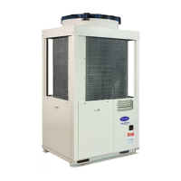
30AWH012_) (Fig. 16)
Troubles of the inverter can be diagnosed by LED
indications on the cycle control P.C. board of the outdoor
unit. Utilize them for various checks.
Before a check, conrm each bit of the DIP switch is set to
OFF position.
LED indication and code checking
LED indication
Cause
LED indication
D800 D801 D802 D803
D800 O: Red
D801 O: Yellow
D802 O: Yellow
D803 O: Yellow
s: Flashing
:O
: On
Heat exchanger sensor (TE) error
Suction sensor (TS) error
Hot gas discharge sensor (TD) error
High-pressure protection error
Outdoor air temperature sensor error (TO)
Outdoor motorised fan error DC
Communication error between IPDU (Abnormal stop)
High-pressure release operation
Discharge temp. error: Hot gas is too high
EEPROM error
Communication error between IPDU (No abnormal stop)
s
G-Tr short-circuit protection
s
Detect circuit error
s s
Current sensor error
s
Comp. lock error
s
s
Comp. break down
Board position:
See g. 16

 Loading...


