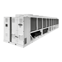
3.3 - 30KAV-ZE 450A & 500A, without hydraulic module
2261 HT
5578 HT
1500
1500
1500
1500
2324 HT
500
500
500
500
B
B
B
B
C
C
C
C
3.4 - 30KAV-ZE 450A & 500A, with hydraulic module
2261 HT
5733 HT
1500
1500
1500
1500
2324 HT
500
500
500
500
B
B
B
B
C
C
C
C
Key
NOTE:
Non-contractual drawings.
Refer to the unit name plate to nd out the machine weight.
Refer to the certied dimensional drawings (appendix 4),
provided with the unit or available on request, when
designing an installation.
Please refer to the certified dimensional drawings
(appendix 4) for the positioning of the xing points, weight
distribution points and centre of gravity coordinates.
If the installation comprises several units or if these are
located close to walls, refer to sections 2.4 - Proximity to
walls and 2.6 - Installation of multiple chillers, to determine
the space required.
All dimensions are given in mm
B
Clearances required for maintenance (see Note)
C
Potentially ammable zone around the machine
Water inlet for standard units
Water outlet for standard units
Air outlet, do not obstruct
Power supply connection
Sling points
3 - DIMENSIONS, CLEARANCES
16

 Loading...