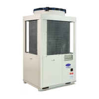
30RB/30RQ
GB - 7
ENGLISH
General information and hydronic module
1
2
3
4
5
6
7
8
9
10
IN
IN
OUT
1 automatic purge
2 pressure gauge for
hydraulic circuit static
pressure
3 hydronic module drain
valve
4 hydronic module pump
5 safety valve
6 ow switch
7 expansion vessel
8 mesh lter
9 pressure reducer (optional)
10 on/o valve (optional)
Hydronic module for 30RB/30RQ017-021 unit
Water connections
Typical water circuit diagram for units without hydronic module
1
2
3
4
5
6
7
8
9
10
IN
IN
OUT
1 automatic purge
2 pressure gauge for
hydraulic circuit static
pressure
3 hydronic module drain
valve
4 hydronic module pump
5 safety valve
Hydronic module for 30RB/30RQ026-033 unit
Hydronic module
The hydronic module is factory-installed.
This eliminates the need to install the necessary components
on-site, making the unit more compact and easy to install.
6 ow switch
7 expansion vessel
8 mesh lter
9 pressure reducer (optional)
10 on/o valve (optional)
Legend for units without
hydronic module:
1 30RB - RQ unit without
hydronic module
2 fan coil units
3 water circulating pump
5 expansion vessel
6 pressure gauges
7 manual shut-o valves
8 mesh lter
9 pressure couplings
10 thermometers
11 ow switch
12 automatic purge valve
13 hydraulic circuit drain
valve
14 charge valve
15 exible coupling
16 safety valve
17 plate-type heat exchanger
drain valve
 Loading...