29
11.2.2 - Condenser and oil separator
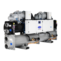
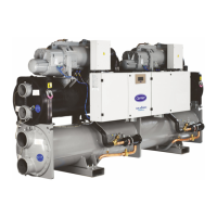
The 30XW chiller uses a heat exchanger that is a combination
condenser and oil separator. It is mounted below the
evaporator. Discharge gas leaves the compressor and ows
through an external mufer to the oil separator, which is
the upper portion of the heat exchanger. It enters the top
of the separator where oil is removed, and then ows to
the bottom portion of the vessel, where gas is condensed
and subcooled. One vessel is used to serve both refrigerant
circuits. There is a center tube sheet which separates the
two refrigerant circuits. The tubes are 3/4” or 1” diameter
internally and externally nned copper tubes.
There is just one water circuit with two water passes (one
pass with option 102C, please refer to chapter 6.5). For the
Heat Machine units the condenser shell can have a polyure-
thane foam thermal insulation (option 86) and a water
drain and purge.
It has been tested and stamped in accordance with applicable
pressure codes. The maximum standard relative operating
pressure is 2100 kPa for the refrigerant-side and 1000 kPa
for the water-side. These pressures can be different depending
on the code applied. The water connection of the heat
exchanger is a Victaulic connection.
11.2.3 - Economiser function (depending on model)
The economiser function includes a liquid line valve, a lter
drier, two electronic expansion valves (EXVs), a plate heat
exchanger as well as protection devices (fuse or valve).
At the condenser outlet a part of the liquid is expanded via
the secondary EXV in one of the heat exchanger circuits
and then returns as a gas. This expansion permits increase
of the liquid sub-cooling of the rest of the ow that pene-
trates the evaporator via the principal EXV. This permits
increasing the cooling capacity of the system as well as its
efciency.
30XW units are equipped with high-pressure safety switches.
In accordance with the applicable code the high-pressure
switches with manual reset, called PZH (former DBK),
may be backed up by high-pressure switches that require
resetting with a tool. The high-pressure switches that
require resetting with a tool are called PZHH (former
SDBK). If a PZHH cuts out, the corresponding PZH in
the same compressor is faulty and must be replaced. The
PZHH must be reset with a blunt tool with a diameter of
less than 6 mm. Insert this tool into the opening on the
pressure switch and push the reset button in this location.
These pressure switches are located at the discharge of each
compressor.
The EXV is equipped with a stepper motor (2785 to 3690
steps, depending on the model) that is controlled via the
EXV board.
The EXV is also equipped with a sightglass that permits
verication of the mechanism movement and the presence
of the liquid gasket.
Located on the EXV, permits control of the unit charge and
indicates moisture in the circuit. The presence of bubbles in
the sight-glass indicates an insufcient charge or non-con-
densables in the system. The presence of moisture changes
the colour of the indicator paper in the sight-glass.
The role of the lter drier is to keep the circuit clean and
moisture-free. The moisture indicator shows, when it is
necessary to change the element. A difference in tempera-
ture between the lter inlet and outlet shows that the
element is dirty.
The units use thermistors to measure the temperature, and
pressure transducers to control and regulate system
opera-tion (see 30XA/30XW Pro-Dialog Control IOM for
a more detailed explanation).

 Loading...


