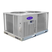
The 38AUQ unit requires an external temperature control
device. This device can be a thermostat (field-supplied) or
a PremierLink controller (available as a field-installed
accessory, for use on a Carrier Comfort Network or as a
stand alone control).
Thermostat --
Install a Carrier-approved accessory thermostat according
to installation instructions included with the accessory.
For complete economizer function, select a two--stage
cooling thermostat.
38AUQ unit control system requires a conventional
electric thermostat that will energize the G terminal on a
call for Cool and Heat mode. Do not configure the
thermostat a a heat pump type; Heat mode will not work
with a thermostat configured for heat pump.
Locate the thermostat accessory on a solid wall in the
conditioned space to sense average temperature in
accordance with the thermostat installation instructions.
If the thermostat contains a logic circuit requiring 24-v
power, use a thermostat cable or equivalent single leads of
different colors with minimum of five leads between the
38AUQ unit's outdoor unit connection board and the
indoor unit connection board. If the thermostat does not
require a 24-v source (no "C" connection required), use a
thermostat cable or equivalent with minimum of four
leads. One additional lead is required between the indoor
unit connection board and the thermostat for terminal G.
If the accessory electric heat is used, one additional wire
is required between the indoor unit connection board and
the thermostat for terminal W2. Check the thermostat
installation instructions for additional features which
might require additional conductors in the cable.
For wire runs up to 50 ft. (15 m), use no. 18 AWG
(American Wire Gage) insulated wire (35°C minimum).
For 50 to 75 ft. (15 to 23 m), use no. 16 AWG insulated
wire (35°C minimum). For over 75 ft. (23 m), use no. 14
AWG insulated wire (35°C minimum). All wire sizes
larger than no. 18 AWG cannot be directly connected to
the thermostat and will require a junction box and splice
at the thermostat.
PremierLink (accessory installation) - Refer to Form
33CS-67SI for details on connecting the PremierLink
controller and its various sensors.
THERMOSTAT
___
___
Q
l
L----
...... i
-i
I I
r
1 1
1
___I [-_---
I
' ,]-;:
I i/1
/1" t___
,
--J __
I r't
I I
I I
I I
I I
r. -- -- /-- --t
t
[
I
INDOOR UNIT
CONNECTION
BOARD{TB
k>
q>
q>
.q>
9
10
@
OUTDOOR UNIT
CONNECTION
BOARD(TB
q>
3®
_Q
__ 7©
L _ [_]... 9
.@
10
@
l
I
I
1
1
1
1
HEAT PUMP INDOOR UNIT
ELECTRIC HEATER
HEAT POMP INDOOR JNIT
WITH ELECTRIC HEATER -
THERMOSTAT CONNECTIONS
C11039
Fig. 13 - Typical Remote Thermostat Connections
External Control Devices --
The 38AUQ control transformers provide 24-v NEC Class 2
power sources to energize external control devices. These
devices will include the indoor fan motor contactor (or
control relay). These devices may also include a liquid line
solenoid vane, economizer control relay, supplemental
electric heater contactors or control relays and other devices
selected by system designer.
Control transformer TRAN1 provides control power through
terminal R to C on the 38AUQ's outdoor unit field
connection terminal strip for supply fan motor interlock.
This source may also be used to energize economizer control
relay and electric heater contactors or relays. Maximum
available power is 50 va. Check concurrent loadings by
external control devices. If the maximum concurrent loading
exceeds 50 va, purchase and install the accessory
Transformer-Relay package (available for 208/230 and
460-v units).
Control transformer TRAN2 provides control power through
terminal A1 (9) to C for the liquid line solenoid. Maximum
available power is 15 va. This output is switched ON/OFF
by the Solenoid Valve Relay (field-supplied, use Carrier
Service Part PNO HN61PC005).
15

 Loading...