– 72 –
FILE NO. SVM-05010
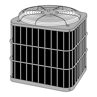
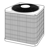
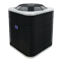
10-4. Outdoor Unit (38HNR024-713)
1) Stop the operation of the air conditioner and turn off
its main power supply or remove the power supply
cord.
2) Remove the electrical parts cover.
(4 screws ∅4 x 10L)
3) Remove 2 cord clamps (4 screws ∅4 x 22L) and
disconnect the power supply cord and connecting
cable after removing 6 screwson on the terminal
block and 1 ground screw on the electrical parts
base.
4) Remove the top cabinet. (7 screws ∅4 x 10L)
5) Remove the front cabinet. (2 screws ∅4 x 10L)
6) Remove the side cabinet
(4 screws ∅4 x 10L & 2 screws ∅4 x 14L)
1) Perform the common procedure 1
2) Remove the capacitor band. (1 screw ∅4 x 10L)
3) Disconnect the lead wires from the capacitor
terminal.
1) Perform the common procedure 1
2) Remove the fixing screw. (1 screw ∅4 x 10L)
3) Disconnect the lead wires from the capacitor
terminal.
1) Perform the common procedure 1
2) Remove the fixing screw. (2 screws ∅4 x 10L)
3) Disconnect the lead wires from the terminal.
1) Perform the common procedure 1
2) Remove the fixing screw. (2 screws ∅4 x 10L)
3) Disconnect the housing from the P.C. Board.
1) Perform the common procedure 1
2) Disconnect the lead wires from the P.C. Board.
3) Remove P.C.Board after unhooking 4 clams.
1 Common
procedure
2 Running
capacitor
for compressor
3 Running
capacitor
for fan motor
4 Magnetic
contactor
5 Transformer
6 P.C. Board
No. Part name Procedures Remarks
Front cabinet Side cabinet
Top cabinet
Electrical
parts cover
4 screws ∅4 x 22L
P.C. Board
Running capacitor
for compressor
Magnetic contactor
Running capacitor
for fan motor
Transformer
 Loading...