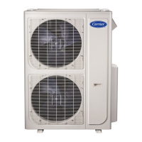
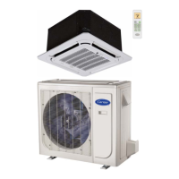
pump model.
CODE PART NAME
L_IN FireWire L input terminal
CN11 Zero line N input terminal
CN16 Internal and external communication line interface
CN6 Indoor fan interface
CN4 Fan feedback interface
CN5 Stepper motor interface
P_1 Ground interface
CN8 Room temperature sensor interface
CN9 Pipe temperature sensor interface
CN10A Display interface
CN14 Compressor top temperature sensor (optional)
CN15 Exhaust temperature sensor
CN16 Outdoor temperature & condenser pipe temperature sensor
CN26,CN28 Four way valve control port
CN10 AC fan output port
CN32,CN34 Electric heating wire line N
CN31,CN33 Electric heating wire line L
CN4 Power L input terminal
CN5 Power N input terminal
CN6 Ground wire
CN7 Communic ation line
N-B Power L input terminal
CN2,CN3 Reactor connected line port
CN17 Test panel interface
U V W Compressor connection port
Fig. 7 – Wiring Diagram 38/40MFC/MFQ012 (208-- 230V)

 Loading...


