Do you have a question about the Carrier 38QUS042DS5 series and is the answer not in the manual?
| Heating Seasonal Performance Factor (HSPF) | 9.0 |
|---|---|
| Refrigerant | R-410A |
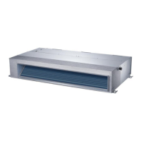
| Indoor Unit Type | Ducted |
| Cooling Capacity | 42000 BTU/h |
| Heating Capacity | 42000 BTU/h |
| Voltage | 208/230V |
Unit types, images, and model numbers for compact four-way cassette units.
Unit types, images, and model numbers for super slim cassette units.
Unit types, images, and model numbers for console units.
Unit types, images, and model numbers for A5 and A6 ducted units.
Wiring diagrams for specific outdoor unit models.
Wiring diagram for 38QUS027DS3* outdoor unit.
Wiring diagram for 38QUS036DS4* outdoor unit.
Wiring diagram for 38QUS042DS5* outdoor unit.
Indoor wiring diagrams for Hi-wall, cassette, console, and other models.
Diagrams of refrigeration circuits for 1-drive-2 and 1-drive-3 systems.
Diagrams of refrigeration circuits for 1-drive-2 and 1-drive-3 systems.
Diagrams of refrigeration circuits for 1-drive-4 and 1-drive-5 systems.
Diagrams of refrigeration circuits for 1-drive-4 and 1-drive-5 systems.
Wiring diagrams for specific outdoor unit models.
Wiring diagram for 38QUS027DS3* outdoor unit.
Wiring diagram for 38QUS036DS4* outdoor unit.
Wiring diagram for 38QUS042DS5* outdoor unit.
Covers compressor, voltage, current, temperature, communication, and ambient protections.
Lists indoor unit error codes and troubleshooting flowcharts.
Lists outdoor unit error codes and their LED status for outdoor units.
Flowcharts for diagnosing indoor and outdoor unit issues like EEPROM, communication, and fan speed.
Procedure and resistance value tables for checking temperature sensors.
Procedures for checking compressor resistance.
Procedures for checking IPM continuity using a digital tester.