7
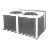
Fig. 3 - Dimensions, mm
38XTZ 014
Outdoor air
discharge
Outdoor air
discharge
Outdoor
air inlet
Suction line
connection 1-1/8"
Rear view
Liquid line
connection 5/8"
Left-hand side view
Power supply
Main disconnect switch
Control box
Compressor
access panel
Front view
Refrigerant line
connections
Fans
Refrigerant-air heat exchanger
Compressor
Control box
Outdoor
air inlet
Plan view
Profile view - unit base
4 anchor and fixing
holes ø 12 mm
4 lifting and transport
holes ø 16 mm
When designing an installation, always use up-to-date drawings, available from your local Carrier office.
Note:
Rain water is drained through
holes in the lower part of the
base under the outdoor unit
heat exchanger and the fans.
 Loading...


