40 GKX
GB - 10
IMPORTANT for units equipped with electric heater:
The unit is equipped with two thermostats: one with automatic reset
and one with manual (electric) reset that can be reactivated by
switching the power supply off and then on.
SYSTEM CONFIGURATION
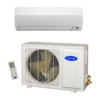
IMPORTANT:
Prior to making the electrical connections, set the switch A
shown in the drawing as follows:
position 1 for cooling only unit;
position 2 for heat pump unit.
A
Electrical connections
If errors are made during the operation previously described, switch
off the main power supply, reposition switch A in the correct position
and then switch the power on.
Connect the power cables to terminal box connectors in accordance
with the wiring diagram and tighten firmly.
IMPORTANT:
• Main power supply comes from outdoor unit.
• Make ground connection prior to any other electrical
connections.
• If the indoor unit is fitted with an electric heater, this must have a
separate power supply.
Ensure that the mains supply connection is made through a switch
that disconnects all poles, with a contact gap of a least 3 mm.
• Make the electrical connections between units prior to proceeding
to the main supply unit connection.
Ensure that the mains supply connection is made through a
switch that disconnects all poles, with a contact gap of a
least 3 mm.
• Fix the power cable of the electrical resistances under the single
cable clamp. (fig. “E”).
Make certain that the YELLOW/GREEN cable is stripped back
further than the others.
IMPORTANT (for heat pump units):
• Check the terminal block in the outdoor unit control panel
to define the electrical connections:
The indoor unit control panel is supplied with a resistor E
factory-connected between terminals “S1” and “S2”.
If the outdoor unit terminal block is supplied without terminals
“S1” and “S2” ,
make the electrical connections as per Fig. A,
leaving resistor E connected.
If outdoor unit terminal block is provided with terminals “S1”
and “S2”, remove resistor E and make electrical connections
as per
Fig. B.
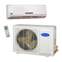
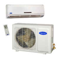
CONTROL PANEL
mod. 12 - 18 - 24
Control panel can be reached by opening the grille and removing its
metal cover by 4 screws.
a
b
c
d
e
f
g
h
i
C
B
A
CLR
CA
CV
CG
CP
R
C
W2
O
Y
S2
S1
a Condenser
b Ground connection screws
c Internec board
d Auxiliary board
e Outdoor unit connection
terminal board
CA
CLR
CV
CP CP
f
c
b
h
C
a
i
g
A
B
e d
f Key panel
g Relay board (only on models
with electric heater)
h Transformer
i Holes for fixing panel in
position
Fan connector
LED/RECEIVER connector
Float connector
Pump connector
Louvre connector
A. Electric heater supply
connection
B. Outdoor unit connection
C. Polarised connectors
CP
CG
CA
CV
CLR
CONTROL PANEL
mod. 28 - 36 - 48 - 60
Key panel
 Loading...