Run Power Wiring for Indoor Unit
Be sure field wiring complies with local building codes and NEC,
and unit voltage is within linfits shown in Table 11 and Table 12.
Contact local power company for correction of improper line
voltage.
ELECTRICALSHOCK HAZARD
Failure to follow this warning could result in personal injury
or death.
Before installing, modifying, or servicing system, main
electrical disconnect switch nmst be in the OFF position.
There nmy be more than 1 disconnect switch. Lock out and
tag switch with a suitable warning label.
[]NIT DAMAGE HAZARD
Failure to follow this caution may result in equipment damage
or improper operation.
Unit failure as a result of operation on improper line voltage or
excessive phase imbalance constitutes abuse and may cause
damage to electrical components. Such operation could void
any applicable Carrier warranty.
NOTE: Use copper wire only between disconnect switch(es)
and unit.
NOTE: Install branch circuit disconnect of adequate size to
handle unit starting current per NEC. Locate disconnect
within sight of, and readily accessible from, unit, per section
440-14 of NEC. Some codes allow indoor unit to share
disconnect with outdoor unit if disconnect can be locked; check
local code before installing in this manner.
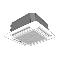
The 40KMC/KMQ units require their own power supply.
1. Locate the indoor power supply.
2. Locate and install disconnect switch per NEC and local
codes.
3. Run power supply wiring to disconnect switch.
4. Run power wiring from disconnect switch to control box
area. Use copper wire only between the disconnect switch
and unit. Use minimum 60°C wires for field power con-
nection.
5. Remove the external control box cover.
6. Place wiring through the 7/8 in. or 1-1/8 in. knockouts on
the bottom and on the right hand side of the external control
box (high voltage side). See Fig. 24 and Fig. 25.
15
 Loading...