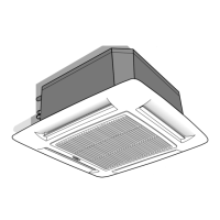
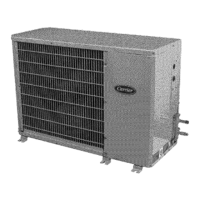
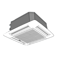
40KQV
GB - 3
ENGLISH
Table IV: Components required for a complete installation
Name Specification
Connection pipe
40KQV050 Ø (1/2") 12.70 mm (Gas) / Ø (1/4") 6.35 mm (Liquid)
40KQV080,110, 130 Ø (5/8") 15.90 mm (Gas) / Ø (3/8") 9.52 mm (Liquid)
Wall sleeve
—
Wall cap
—
Finishing tape PVC
film
Fastening tape
—
Tube insulation
—
Drain hose
I.D. 16 - 17 mm
Sealer putty
—
- Electrical connecting cable 1. Cable type: A07RN- F, synthetic rubber insulation with Neoprene coating,
between indoor and outdoor unit according to EN 60335-2-40 standards.
Technical data
Table II:
Material supplied
Description Quantity Use
Installation instructions 1 Indoor unit installation
Owner's Manual 1 Correct use
Fresh air intake baffle 1 Air renewal
Note:
For power supply wire size and delay type fuses, refer to the outdoor unit
installation instructions.
Table I: Nominal data
POWER INPUT (WATT)
Heat pump
Unit Cooling Heating
40KQV050 105 105
40KQV080 107 107
40KQV110 131 131
40KQV130 178 178
Table III: Operating limits
Cooling / Heating Refer to outdoor unit installation manual.
Nominal single-phase voltage 220-240V
~
50Hz
Main power supply
Operating voltage limits min. 198V – max. 264V

 Loading...


