14
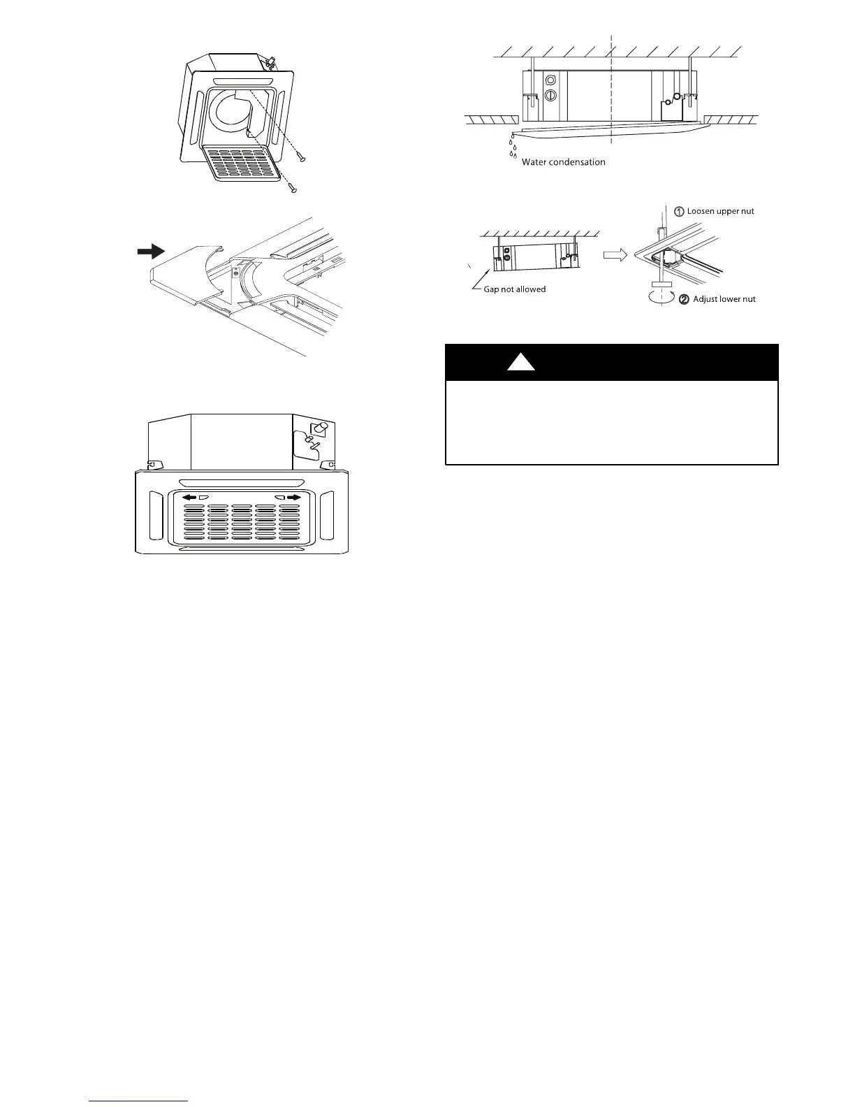
6. Fasten the control box lid with two screws.
Fig. 30 - Fasten the Control Box Lid
Fig. 31 - Fasten Installation Covers
7. Close the intake grille, and close the two grille hooks.
Fig. 32 - Close the Intake Grille
Fig. 33 - Adjust Height of Indoor Unit
Fig. 34 - Adjust Height of Indoor Unit
UNIT DAMAGE HAZARD
If the unit is not hung correctly and a gap exists, the
unit's height must be adjusted to ensure proper
function, the unit's height can be adjusted by
loosening the upper nut and adjusting the lower nut.
CAUTION
!
NOTE: If the height of the indoor unit needs to be adjusted, you
can do so through the openings at the panel’s four corners. Make
sure that the internal wiring and drainpipe are not affected by this
adjustment.
ELECTRICAL DATA
Table 5—Electrical Data
UNIT SIZE
OPER. VOLTAGE
INDOOR FAN
MAX / MIN*
V-PH-HZ FLA HP W
9
253 / 187
-
0.146 0.061 46
Refer to outdoor unit installation
12 0.146 0.061 46
18 0.146 0.061 46
Refer to outdoor unit installation
–
24
-
0.332 0.057 58
–
Indoor unit powered by the outdoor unit
36 0.8 0.169 141
48 1.6 0.231 232
*Permissible limits of the voltage range at which the unit will operate satisfactorily.
LEGEND
FLA - Full Load Amps

 Loading...