7
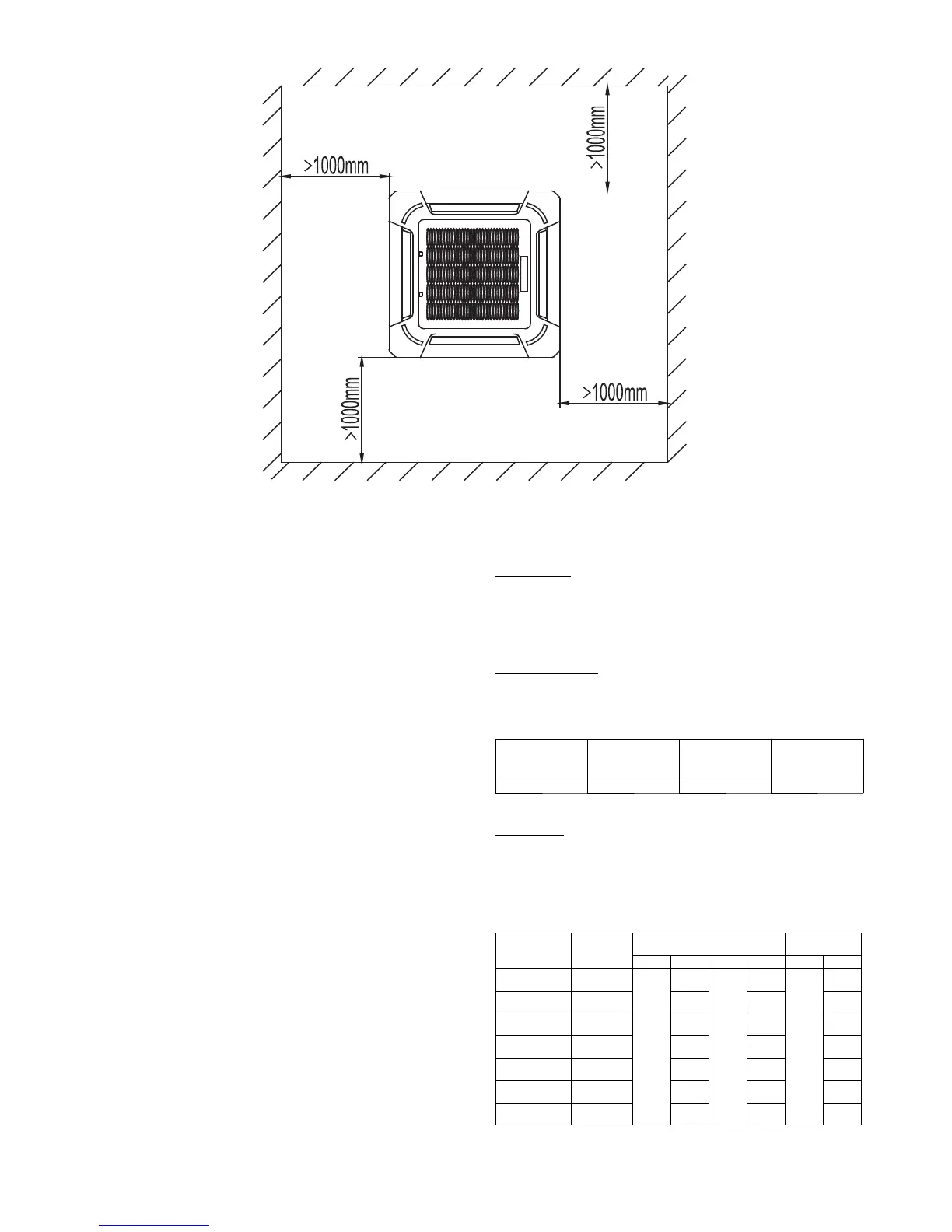
CLEARANCES -- INDOOR
A150152
Fig. 9 -- 40MKC**B, 40MKQ**B Unit Clearance
CLEARANCES -- OUTDOOR
1. Single Unit Applications: With coil facing wall: Allow 6”
(152.4mm) mini mum cl earance on c oi l si de and coil end and
20” (504.0 mm) minimum cl earance on fa n side. A l low 24”
(609.6 mm) mini m um c l earance on c om pr es s or end for
service.
2. With fan facing wall: Al low 8” (203. 2 mm) minim um
clearance on fan si de and coil end and 20” (504. 0 mm)
mi ni m um clearance on c oil s ide. Al low 24” (609.6 mm)
minimum clearance on compressor end for service when units
are stacked or the r e is less than 40” ( 1016 mm) of cl earance
above the unit. If there is 40” (1016 mm) cl earance above unit
and the top panel is accessible for removal allow 8” (203.2
mm) minimum clearance on compressor end for service.
3. Multi--unit Applications: Allow 24” ( 609.6 mm) mini m um
clearance between fan and coil sides of multiple units. Arrange
units so dis charge of one does not ent er inl et of another. Allow
24” (609.6 mm) mini mum clearance on com pressor end when
units ar e stacked or there i s l ess than 40” (1016 mm) of
clearance above the unit . If the re is 40” (1016 mm) clearance
above unit and the top panel is accessible for removal allow 8”
(203.2 mm) mini m um c l earance on c om pr es s or end for
service. When two units are installed end to end with the coil
ends facing each other allow 12” (304. 8 mm) minimum
clearance between units.
IMPORTANT: When installing multiple units, ensure the
discharge air from one unit is not drawn into another unit. When
installing single or multiple units in an alcove, roof well, or
partially enclosed area, ensure there is adequate ventilation to
prevent recirculation of discharge air.
SYSTEM REQUIREMENTS
Clearances
Allow sufficient space around the indoor and outdoor unit for
proper airflow circulation and servicing. Refer to Fig.9 and the
outdoor unit clearance section for minimum required clearances.
Piping: Piping and insulation is field supplied.
Piping Lengths
The minimum length between the indoor and outdoor units is 10 ft
(3 m). Refer to table 9 for the maximum lengths allowed.
Table 9 – Maximum Refrigerant Line Lengths
Unit Size
Max Line
Length* ft(m
Max Elevation
(ID over OD)
ft(m)
Max
Elevation (OD
overID)ft(m)
18K-34K 250 (76.2) 65 (19.8) 200 (61)
Note:Forlengthsgreaterthan25ft(7.6m),refertotheResidential Long
Line G uide.
Pipe Sizes
In some models, indoor unit and/or outdoor unit pipe sizes may
differ from those in TXV connections. Coupling is required in
those cases. See Table 10 for complete list of tube sizes to identify
coupling needs.
Table10–PipeSizes
Indoor Unit Outdoor Unit
Indoor Unit Tube
Sizes (in)
TXV Kit Tube
Sizes (in)
Outdoor Unit
Tube Size (in)
Liquid Vapor Liquid Va po r Liquid Vapor
40MKCB18C----3
24AHA418
124ANS018
3/8
5/8
3/8
5/8
3/8
5/8
40MKCB34C----3
24AHA424
124ANS024
3/4 3/4 3/4
40MKCB34C----3
24AHA430
124ANS030
3/4 3/4 3/4
40MKCB34C----3
24AHA436
124ANS036
3/4 3/4 7/8
40MKQB34C-- -- 3
25HHA424
224ANS024
3/4 3/4 3/4
40MKQB34C-- -- 3
25HHA430
224ANS030
3/4 3/4 3/4
40MKQB34C-- -- 3
25HHA436
224ANS036
3/4 3/4 7/8
Note:Both lines need to be insulated using at least 1/2 inch closed foam
insulation.
 Loading...