9
INSTALLATION
Complete Pr e--installation Checks
1. Unpack Unit -- Store the indoor and outdoor units in the orig-
inal packaging until it is moved to the final site for installation.
Whe n unpacking indoor unit , be careful not to li ft unit by con-
densate drain dis charge pipe or by refrigerant conne ctions.
2. Ins pect Shipment -- Upon receipt of shipment, check the in-
door and outdoor units for damage . I f there is any dam age,
forwa r d claim pape r s directly to the tr ansportation com pany.
Ma nufacturer is not re sponsible for damage incurred in transit .
3. Inspect Parts Supplied With Units – Check all items
against parts list (see the PARTS LIST section). If any items
are missing, notify your distributor or manufacturer office.
To prevent loss or damage, leave all parts in original pack-
ages until installation.
Consider System Requirements
1. Consult local building codes and NEC for special installa-
tion requirements.
2. When deciding the location of the indoor and outdoor units,
ensure that the piping run does not exceed the allowed dis-
tances listed in Table 9.
3. Make sure the indoor and outdoor units are easily accessible
to electrical power.
4. Allow sufficient clearances for airflow, wiring, refrigerant
piping, and servicing the unit (see the ”CLEARANCES --
INDOOR” and “CLEARANCES -- OUTDOOR” sections).
5. Condensate piping can be directed through the inside wall
to an approved drain or straight outside.
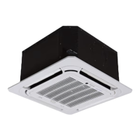
INSTALL INDOOR UNIT
Plan the installation carefully before you begin.
1. Select indoor unit location.
a. Where it is out of direct sunlight.
b. Where the airflow is not blocked.
c. Where an optimum air distribution is ensured.
d. Where the condensate can drain correctly and safely.
e. A ceiling that prevents vibration and is strong enough to
hold the product weight.
f. Maintain sufficient clearance around the indoor unit for
maintenance and servicing. Refer to the clearances sec-
tion of this document.
g. Where the air filter can be removed and cleaned easily.
h. Where the piping between the indoor and outdoor units
is within the allowable limits.
i. I nstall the indoor unit 1m or more awa y fr om the TV or
radio to pre vent the s creen fr om being distorted or nois e
from being generated.
j. Install the indoor unit as far away as possible from fluo-
rescent and incandescent lights so that the remote con-
trol can be operated well.
k. Do not install units too close to humid conditions.
2. TXV Installation
a. Location -- The TXV kit can be affixed directly to the
indoor unit or anywhere between 12 to 18 inches from
the indoor unit pipe connection.
!
CAUTION
Failure to follow the following caution may result in equipment
damage or improper operation.
The TXV kit needs to be installation at most 12 to 18 inches
from the indoor unit pipe connection.
b. The TXV contains a label specifying the allowed flow
direction. See below for allowed and not allowed flow
directions.
!
CAUTION
Failure to follow the following caution may result in equipment
damage or improper operation. One of the two arrows on the
TXV part number label must point up when installed.
Install unit such that the refrigerant flow directions is in any of
the two allowed directions.
Indoor unit
connection
Outdoor unit
connection
Indoor unit
connection
Outdoor unit
connection
Arrows on TXV label pointing
upward and to the right
Arrows on TXV label pointing
upward and to the left
Fig. 10 -- Allowed TXV installation direction per label at-
tached to TXV
Refrigerant
flow direction
To
indoor
unit
To
outdoor
unit
Fig. 11 -- TXV Flow Direction
 Loading...