– 24 –
5-4. 42TAR018-723 / 38TAR018-723
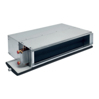
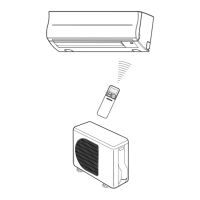
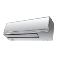
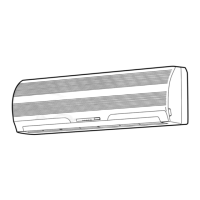
Indoor unit
Cross flow fan
Compressor
Condenser
Propeller fan
Outdoor unit
PH290X2C-4FT1
O.D.:15.88 mm O.D.:6.35 mm
Packed valve
(∅15.88)
Packed valve
(∅6.35)
T
P
Refrigerant
R22 1.47 kg
Evaporator
0.39 m
(Connecting pipe)
∅15.88
0.49 m
(Connecting pipe)
∅6.35
Mark ( ) means check points of Gas Leak
Capillary tube
∅2.0 x 800 s
Accumulator
Note : Measure the heat exchanger temperature at the center of U-bend. (By means of TC sensor.)
Ambient temp.
conditions DB/WB
(°C)
Indoor Outdoor
Standard 0.5 10.0 High 27/19 35/24
Cooling High temperature 0.6 12.0 High 32/23 43/26
Low temperature 0.3 2.0 Low 21/15 21/15
Fan speed
(indoor)
50 Hz
Standard
pressure
P
(MPaG)
Surface temp. of heat
exchanger interchanging
pipe
T
(°C)
FILE NO. SVM-05010
 Loading...