23
42N_S 42N_E
English
Installation
Receipt of unit
t Check that packaging is undamaged.
t Unpack unit and check immediately for damage during transportation.
t Packaging contains the base unit and, if supplied, the unit cabinet.
t Verify that all components ordered are supplied.
Unit preparation
t Take out and position template printed on the packaging. It is
advisable to keep cabinet packed until installation is complete.
t To install the cabinet, position it onto the base unit and x it to the
special tabs on the unit rear side and then secure it with the two
screws supplied (See g.14-15).
t If the unit is installed at 150 mm from the oor or lower, use the
angles supplied with the base unit to prevent the user from touching
the moving parts (See g.14-15).
t If, instead, the unit is installed higher than 150 mm from the oor, use
the rear closing grille kit (code 42N0954-42N0955-42N0956-42N0957)
according to the unit size. For horizontal installation at more than
2.5 meters from the oor, the angles supplied need not be used. For
horizontal installation at more than 2.5 meters from the oor, the
angles supplied need not be used.
Installation
t Before proceeding to unit installation, it is recommended to assemble
the accessories according to the instructions supplied with the kit.
t It is advisable to lock the cover on the opposite side to the control or
on both sides if the control is not positioned on the unit.
t Knock out the prepunched part of the cover to insert the screw.
t Furthermore it is possible to lock the control cover.
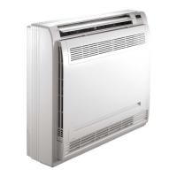
Floor-mounted vertical unit (See g. 18)
The unit is provided with supporting feet and cover panels (models with
cabinet).
t For positioning and drilling use the template printed on the packaging.
t Drill four holes for the screw anchors close to the upper and lower hooks.
t Install the supporting feet by inserting the special tab into the
corresponding slot on the unit plate (See g. 17). Centre the
two indentations and secure each supporting feet using the
corresponding clips supplied with the kit.
t If a baseboard is mounted onto the wall, remove the pre-cut tab from
the cover panel. Install the cover panels by hooking them to the slots
on the cabinet lower part and secure them with the screws supplied.
t Position unit to wall and secure it with screws. To facilitate cabinet
installation, it is suggested to use athead screws.
t To complete the installation make electrical and water connections as
per the diagram inside the control box panel. When all connections
have been made, install the cabinet as previously described.
t Start-up of all units supplied without cabinet (42NF – 42NP) should
be carried out by the installer according to safety directions for easy
access to live and moving parts provided for by EN 60335-1 and EN
60335-2-40 standards (see Fig. 18A and 18B but only as an indicative
example).
WARNING: With wall-to-wall carpet the hole points must be moved up
by 10 mm (as indicated on the template).
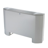
Wall-mounted vertical unit
t This unit is not provided with supporting feet and cover panels.
t Install the unit as indicated above and keep it at least 100 mm from
the oor.
Ceiling-mounted horizontal unit
(See g. 19-20)
t Use the template printed on the packaging for ceiling mounting of
the unit.
Units with cabinet 42NM and 42NZ
t Make four holes for the screw anchors near the four hooks g. 19 (2
side and 2 front hooks).
Concealed units 42NF and 42NP
t Attach the two brackets supplied for horizontal installation to the unit,
securing them with the screws as shown in gure 20.
t Make four holes for the screw anchors near the four side hooks.
t Hook the unit on the screw anchors in the ceiling and adjust the 4
screws.
t Make certain the fan coil is horizontally levelled.
t Make electrical and water connections and install the cabinet.
Condensate drain
Coil surface condensation formed during the cooling cycle is collected
in a pan purposely placed under the coil and then drained out through
a drain pipe tted on the coil connection side.
A simple exible tube which ts Ø 20 mm is recommended. To facilitate
correct condensate draining, make sure that the drain pipe is not bent
or restricted and that it has the required slope (at least 2%) along its
length. A drain trap is recommended (See g. 9)
Checking
Before unit operation verify that the water ows into the internal
condensate drain pan by pouring some water into it.
If problems are detected, check the drain pipe slope and look for
possible obstructions.

 Loading...