EasyManua.ls Logo

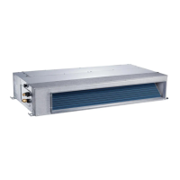
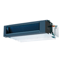
Carrier 42QTD012DS - Ducted Unit Disassembly Instructions; Remove Electronic Control Box; Remove Display Board

Carrier 42QTD012DS
70 pages
To Next Page IconTo Next Page
To Previous Page IconTo Previous Page
Loading...
7
DISASSEMBLY INSTRUCTION
No. Parts name Procedures Remarks
1 Remove the
electronic
control box
1) Screw off the screws to
remove the cover of
electronic control box
2) Disconnect the fan motor
wire, fan capacity wire,
room temperature sensor
wire and evaporator
temperature sensor wire
3) Screw off the screws to
remove electronic
control box
2 Remove the
display
board
1) Remove the cover of
electronic control box
Repeat the operation of step1 of No1
2) Disconnect the display
board wire connected to
PCB
3) Remove the sticker
3
Move the display board
according to the arrow
direction to disassemble
it.
Connector
Plug of room
temperate sensor
and evaporator
temperature sensor
Fan motor wire
Sticker
2 screws
Fan capacity wire

Related product manuals