30
Controls Operation
Before proper control operation can be verified, all other systems
must be operating properly. The correct water and air temperatures
must be present for the control function being tested. Some con-
trols and features are designed to not operate under certain condi-
tions. For example, on a two-pipe cooling/heating system with
auxiliary electric heat, the electric heater cannot be energized with
hot water in the system.
A wide range of controls, electrical options and accessories may
be used with the equipment covered in this manual. Consult the
approved unit submittals, order acknowledgments, and other liter-
ature for detailed information regarding each individual unit and
its controls. Since controls and features may vary from one unit to
another, care should be taken to identify the controls used on each
unit and their proper control sequence. Information provided by
component manufacturers regarding installation, operation, and
maintenance of their individual controls is available upon request.
When changing from one mode to another (cooling to heating or
heating to cooling), it may take some time to actually notice a
change in the leaving air temperature. In addition, some units may
be designed for a very low air temperature rise in heating. Before
declaring a unit inoperative or a component defective, it may be
necessary to verify operation by more than one method.
SERVICE
Each unit on a job will have its own unique operating environment
and conditions which may dictate a maintenance schedule that dif-
fers from other units on a job. A formal schedule of regular main-
tenance and an individual unit log should be established and main-
tained. This will help to achieve the maximum performance and
service life of each unit on the job.
Excessive Condensation on Unit
Running chilled water through a fan coil unit with the unit fan off
can cause excessive condensation. If fan cycling is used, a water
flow control valve should be installed to shut off the water when
the fan stops.
Other methods of control that avoid condensation problems are as
follows:
1. Continuous fan operation with motorized chilled water valve
controlled by a thermostat.
2. Continuous fan operation with thermostat control to switch
fan from high to low speed (instead of off).
To Clean Coil
Coils may be cleaned by removing the filter and brushing the en-
tering air face between fins with a stiff brush. Care should be taken
to not damage coil fins. Brushing should be followed by cleaning
with a vacuum cleaner. If a compressed air source is available, the
coil may also be cleaned by blowing air through the coil fins from
the leaving air face. This should again be followed by vacuuming.
Units provided with the proper type of air filters, replaced regular-
ly, will require less frequent coil cleaning.
Check Drain
Lock open and tag unit electrical service switch.
Check drain pan, drain line and trap before initial start-up and at
start of each cooling season. A standard type pipe cleaner for
3/4 in. ID (Inside Dimensions) pipe can be used to ensure that pipe
is clear of obstruction so that condensate is carried away. Check
the drain line at filter cleaning time during the cooling season. Be
sure that debris has not fallen into unit through supply-air grille.
Should the growth of algae and/or bacteria be a concern, consult
an air conditioning and refrigeration supply organization familiar
with local conditions for chemicals or other solutions available to
control these agents.
Fan Motor Bearings
Lock open and tag unit electrical service switch.
Standard motors are permanently sealed and lubricated. No lubri-
cation is required unless special motors have been supplied or un-
usual operating conditions exist.
Motor/Blower Assembly
The type of fan operation is determined by the control components
and their method of wiring. This may vary from unit to unit. Refer
to the wiring diagram that is attached to each unit for that unit’s in-
dividual operating characteristics.
All motors have permanently lubricated bearings. No field lubri-
cation is required.
Should the assembly require more extensive service, the motor/
blower assembly may be removed from the unit to facilitate such
operations as motor or blower wheel/housing replacement, etc.
Dirt and dust should not be allowed to accumulate on the blower
wheel or housing. This can result in an unbalanced blower wheel
condition which can damage a blower wheel or motor. The wheel
and housing may be cleaned periodically using a vacuum cleaner
and a brush taking care not to dislodge the factory balancing
weights on the blower wheel blades.
Clean Fan Wheel
Lock open and tag unit electrical service switch.
For access to fan assembly, remove front or bottom panel. Fan as-
sembly may be removed from its tracks if unit has a long conduit
lead. Dirt and debris should not be allowed to accumulate on the
blower wheel or housing. This can result in an unbalanced blower
wheel condition which can damage a blower wheel or motor. The
wheel and housing may be cleaned periodically using a vacuum
cleaner and a brush, taking care not to dislodge the factory balanc-
ing weights on the blower wheel blades.
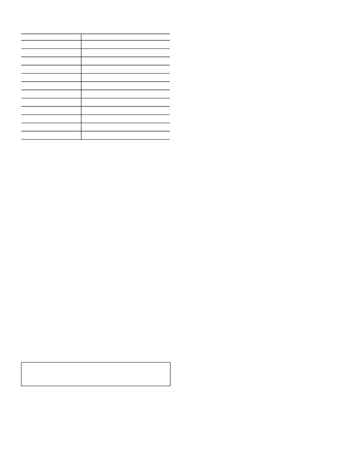
Table 3 — Water Quality Parameters
a,b
NOTE(S):
a. Maximum water operating temperature: 190°F (98°C).
b. Maximum allowable water pressure: 500 psig (3447 kpa).
WATER CONTAINING REQUIRED CONCENTRATION
Sulphate Less than 200 ppm
pH 7.0 to 8.5
Chlorides Less than 200 ppm
Nitrate Less than 100 ppm
Iron Less than 4.5 mg/l
Ammonia Less than
2.0 mg/l
Manganese Less than 0.1 mg/l
Dissolved Solids Less than 1000 mg/l
CaCO
3
Hardness 300 to 500 ppm
CaCO
3
Alkalinity 300 to 500 ppm
Particulate Quantity Less than 10 ppm
Particulate Size 800 micron max
IMPORTANT: Information regarding safety precautions con-
tained in the preface at the beginning of this manual should be
followed during any service and maintenance operations.
 Loading...


