35
12 - FACTORY OPTIONS AND ACCESSORIES
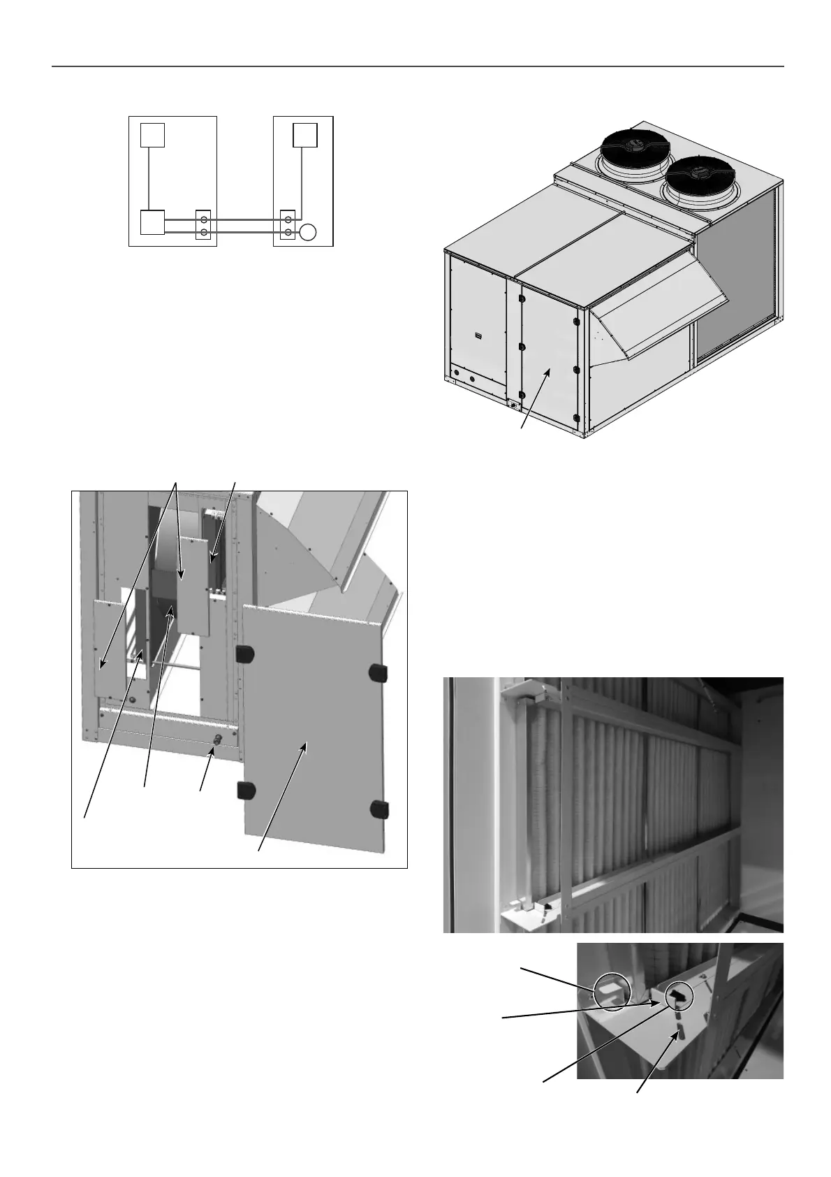
12.4 - Air fi lters
■ These units include G4 gravimetric fi lters standard type, which
can be replaced by:
- Gravimetric fi lters G4 with low pressure drop.
- Gravimetric fi lters G4 standard type + folded opacimetric
fi lters F7.
- Gravimetric filters G4 with low pressure drop + folded
opacimetric fi lters F7.
- Dual-stage of folded opacimetric fi lters: M6+F7 or F7+F9.
■ The access panel to the fi lters incorporates dual locks, they
can function as hinges or can be used to remove the panel.
■ The inside of the heat recovery unit module is accessed via the
left-hand panel (front view), for maintenance tasks concerning
the fi lters and the condensate pan (3/4” M gas threaded plastic
drain connection). This panel features dual locks. Check that
the locks are not blocked. Open the locks with a 4 mm Allen
key (in an anticlockwise direction).
The access panels to the fi lters are secured using M4 Allen
screws.
Note: The general procedure for removing and cleaning the
fi lters is described in chapter “Maintenance”.
Access to the inside of the recovery module
■ The wheel motor can be accessed via the right-hand panel (front
view). This panel is secured using M6 Allen screws.
■ The thickness of the frames is 25 mm for the G4 standard type
and 50 mm for the G4 low pressure drop and all opacimetric
fi lters.
Filters supplied from the factory can be replaced on site by
other types of fi lters with diff erent thickness.
The filter holder structure supports the following filter
combinations: 25 mm, 25 mm + 50 mm, 50 mm + 50 mm.
The fi lter holder structure incorporates a tensioner that can be
moved along a guide to adjust the width according to the chosen
combination. With the help of a locking knob, the position of
the frames is locked after placement.
To extract the frames from each row, simply slide the tab.
Note: the fi lters cleaning procedure is explained in the chapter
of “Maintenance”.
Tab for displacement
of the frames
Tensioner
Locking knob for
the tensioner
Guide
50FC unit Wheel module
2
1
2
1
BOX3
BOX5
RT
W59RRT
W59
VRR
BOX6
CTW
Connection to be made by the customer:
W58
Left-hand panel
Drain
connection
Filters on
the exhaust
air outlet
Access panel to fi lters,
M4 Allen screws
Wheel
Filters on the
fresh air intake
Note: Check that the locks are not blocked. Open them with a
4 mm Allen wrench (in an anti-clockwise direction).
Access panel

 Loading...


