14
CONVENIENCE OUTLET — An optional convenience out-
let provides power for rooftop use. For maintenance personnel
safety, the convenience outlet power is off when the unit dis-
connect is off. Adjacent unit outlets may be used for service
tools. An optional “Hot Outlet” is available from the factory as
a special order item.
NOVAR CONTROLS — Optional Novar controls (ETM
3051) are available for replacement or new construction jobs.
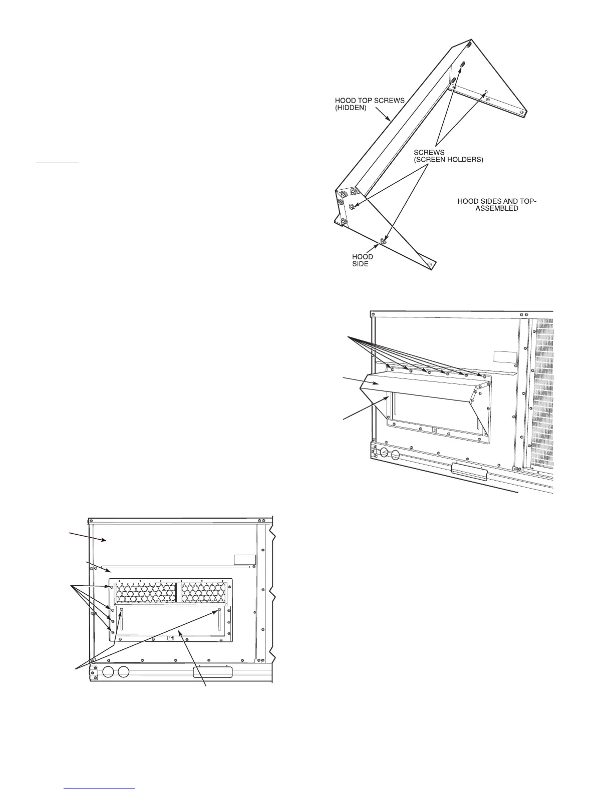
MANUAL OUTDOOR-AIR DAMPER — The outdoor-air
hood and screen are attached to the basepan at the bottom of
the unit for shipping.
Assembly:
1. Determine quantity of ventilation required for building.
Record amount for use in Step 8.
2. Remove filter access panel by raising panel and swinging
panel outward. Panel is now disengaged from track and
can be removed. No tools are required to remove the filter
access panel. Remove outdoor-air opening panel. Save
panels and screws. See Fig. 15.
3. Separate hood and screen from basepan by removing the
screws and brackets securing them. Save all screws and
discard brackets.
4. Replace outdoor air opening panel.
5. Place hood on front of outdoor air opening panel. See
Fig. 16 for hood details. Secure top of hood with the
6 screws removed in Step 3. See Fig. 17.
6. Remove and save 8 screws (4 on each side) from sides of
the manual outdoor-air damper.
7. Align screw holes on hood with screw holes on side of
manual outdoor-air damper. See Fig. 16 and 17. Secure
hood with 8 screws from Step 6.
8. Adjust minimum position setting of the damper blade by
adjusting the manual outdoor-air adjustment screws on
the front of the damper blade. Slide blade vertically until
it is in the appropriate position determined by Fig. 18.
Tighten screws.
9. Remove and save screws currently on sides of hood. In-
sert screen. Secure screen to hood using the screws. See
Fig. 17.
10. Replace filter access panel. Ensure filter access panel
slides along the tracks and is securely engaged.
PREMIERLINK™ CONTROL — The PremierLink control-
ler is compatible with Carrier Comfort Network® (CCN) de-
vices. This control is designed to allow users the access and
ability to change factory-defined settings, thus expanding the
function of the standard unit control board. Carrier’s diagnostic
standard tier display tools such as Navigator™ or Scrolling
Marquee can be used with the PremierLink controller.
The PremierLink controller (see Fig. 19 and 20) requires the
use of a Carrier electronic thermostat or a CCN connection for
time broadcast to initiate its internal timeclock. This is neces-
sary for broadcast of time of day functions (occupied/ unoccu-
pied). No sensors are supplied with the field-mounted Premier-
Link control. The factory-installed PremierLink control in-
cludes only the supply-air sensor (SAT) and the outdoor air
temperature sensor (OAT) as standard. An indoor air quality
(CO
2
) sensor can be added as an option. Refer to Table 5 for
sensor usage. Refer to Fig. 21 for PremierLink controller
wiring. The PremierLink control may be mounted in the
control panel or an area below the control panel.
SCREWS
(SIDE)
MANUAL
OUTDOOR-AIR
ADJUSTMENT
SCREWS
DAMPER
BLADE
FILTER
ACCESS
PANEL
OUTDOOR AIR
OPENING
PANEL
Fig. 15 — Damper Panel with Manual
Outdoor-Air Damper Installed
Fig. 16 — Outdoor-Air Hood Details
SCREW
HOLES
(TOP)
HOOD
HOOD
SCREEN
LOCATION
(SCREEN
NOT
SHOWN)
Fig. 17 — Optional Manual Outdoor-Air
Damper with Hood Attached
 Loading...
