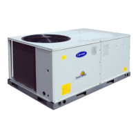
Field Control Wiring – The 50TCM unit requires an external temperature control device. This device can be a
thermostat (field--supplied) or a PremierLink controller (field--installed accessory, for use on a Carrier Comfort
Network or as a standalone control)
Thermostat – Install a Carrier--approved accessory thermostat according to installation instructions included with the
accessory. Select a two--stage cooling thermostat. Locate the thermostat accessory on a solid wall in the conditioned
space to sense average temperature in accordance with the thermostat installation instructions.
If the thermostat contains a logic circuit requiring 24—v power, use a thermostat cable or equivalent single leads of
different colors with minimum of seven leads. If the thermostat does not require a 24--v source (no “C” connection
required), use a thermostat cable or equivalent with minimum of six leads. Check the thermostat installation
instructions for additional features which might require additional conductors in the cable.
For wire runs up to 15 m (50 ft.), use no. 18 AWG (American Wire Gage) insulated wire (35_C minimum). For 15 to 23
m (50 to 75 ft.), use no. 16 AWG insulated wire (35_C minimum). For over 23 m (75 ft.), use no. 14 AWG insulated
wire (35_C minimum). All wire sizes larger than no. 18 AWG cannot be directly connected to the thermostat and will
require a junction box and splice at the thermostat.
Fig. 8 Typical Low-Voltage Control Connections
3.0 – START-UP INSTRUCTIONS
PRIOR to unit start-up use the following instructions and start-up checklist provided on the last page.
3.1– Unit Preparation
Check that unit has been installed in accordance with these installation instructions and all applicable codes.
3.2 – Internal Wiring
Check all electrical connections in unit control boxes; tighten as required.
3.3 – Compressor Mounting
Compressors are internally spring mounted. Do not loosen or remove compressor hold down bolts.
3.4 – Refrigerant Service Ports
Each refrigerant system has a total of 2 Schrader type Service gage ports. One port is located on the suction line,
one on the compressor discharge line, and one on the liquid line. In addition Schrader-type valves are located
underneath the pressure switches. Be sure that caps on the ports are tight.

 Loading...