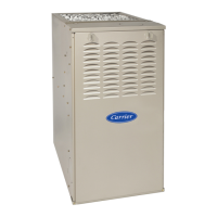
58SU0A (Series 2 & 3): Troubleshooting Guide
Manufacturer reserves the right to change, at any time, specifications and designs without notice and without obligations.
21
Status Code 45 - Control Circuitry Lockout
Indicates the furnace control detected one of the following:
Reset power to clear lockout, If status code reoccurs when power is reapplied, replace furnace control.
CLEAN UP AND STARTUP
WIRING HARNESS – indicated yellow jumper in main plug of harness is damaged or missing:
44.
Referencing the Voltage/Pressure graph located in APPENDIX D, compare the pressure from the slope
manometer to the output signal voltage from the transducer.
EXAMPLE: The graph illustrates that at 1" of negative pressure, the transducer output should be
approximately 1.5 VDC. At 3" of negative pressure, the transducer output should be approximately 3.5
VDC.
45
45. Is the transducer VDC output within +/- 0.15 VDC of expected value? 46 47
46.
You have excessive restriction in combustion airflow. Inspect HX and inducer housing assembly for
blockage
15
47. Replace Transducer 15
48. Turn power off and disconnect jumper wire across R and W thermostat terminals 49
49.
Make sure that all pins and wire leads are intact on connections between the furnace control and the
inducer motor.
50
50.
Connect 1 side of a slope manometer with a tee to the collector box pressure tap. Refer to pressure check
connection illustration in APPENDIX C: Transducer Operational Check
51
51.
Check for proper output of the transducer. To do this, connect a DC voltmeter across terminals PL12-2
GREEN and PL12-3 BLACK (+).
52
52. Turn power ON and jumper the R and W thermostat terminals. 53
53.
Reference APPENDIX D: “Transducer Target Pressures”. Does the transducer feedback voltage (within
+/- 0.15 VDC) and the HX pressure reach expected values?
26 54
54. Turn power off and disconnect jumper wire across R and W thermostat terminals. 55
55. Inspect pressure hose between inducer housing and transducer for cracks or leaks 56
56. Inspect pressure switch hoses and inducer housing port for obstruction 57
57. Inspect inducer housing and reseal to cell panel as needed 58
58. Inspect burner box mounting screw and tighten to 45 in-lbs. if needed. 59
59. If code 42 persists on an intermittent basis, replace the inducer assembly 8
STEP ACTION YES NO GO TO
1. Flame Sense Circuitry Error
2. Software Check Error
3. Gas Valve Relay Stuck Open
STEP ACTION
1.
Start furnace using procedure outlined on Lighting Instructions attached to furnace. Observe operation of furnace through at least 1
complete heating cycle controlled from the room thermostat. Observe cycle for 20 minutes or until a status code is flashed. If status code
flashes, refer to the Index
2.
Recycle as necessary and check thermostat heat anticipator setting, gas input rates, and temperature rises. These procedures are
outlined in the Installation, Start-Up, and Operating Instructions manual.
3. Check operation of safety devices: limit switch and burner thermal switch
4. Put heat off delay setup jumper in its proper positions.
5. Remove tape from the door switch.
6. Replace thermostat leads (if necessary).
7. Set thermostat in AUTO position, calling for heat.
8. Set thermostat to desired temperature.
9. Replace furnace door(s). Clean up

 Loading...
