T--298
3-10
3.6 SERVICE -- UPPER UNIT -- LOW PROFILE
3.6.1 Exterior Cover Removal
CAUTION
Coilfinsaresharp. Usecarewhenremoving
the cover form the base pan to avoid per-
sonal injury.
To remove the exterior cover, do the following:
a. Before working on unit placethe master switch in the
OFF position and disconnect all electrical power.
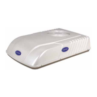
b. Remove (8) screws securing the unit cover to the
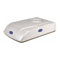
base pan assembly. See Figure 3-26.
c. Carefullylift theexteriorcover off of theunit basepan
assembly.
d. Reverse above procedure for reassembly.
Screws
Screws
Figure 3-26 Cover Assembly -- Low Profile
3.6.2 Upper Scroll Assembly Removal
To remove the upper scroll assembly, do the following:
a. Removeexterior coverassembly. Refer toparagraph
3.6.1.
b. Releasethe(2)front,(2)rear,(1)leftsideand (1)right
sidelockingtabs (SeeFigure 3-27)bypulling backon
the tabs (See Figure 3-28).
c. Remove the screw (1) from the control box cover
(See Figure 3-27).
d. With all (6) locking tabs released and control box
screw removed, lift the upper scroll assembly off of
the lower scroll assembly.
e. Reverse above procedure for reassembly. Ensure all
(6) locking tabs snap shut & lock.
b. b.
b.
b.
b.
b.
c.
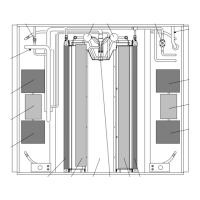
Figure 3-27 Upper Scroll Assembly
Locking Tabs (b.) & Screw Locations (c.)
Figure 3-28 Upper Scroll Assembly
Keeper Tab Release
 Loading...
