T -304
5--1
04/08
SECTION 5
SERVICE
WARNING
Besure to observewarnings listed in thesafetysummary in thefrontof thismanual beforeperform-
ing maintenance on the hvac system
WARNING
Read the entire procedure before beginning work. Park the coach on a level surface, with parking
brake applied. Turn main electrical disconnect switch to the off position.
NOTE
To avoid damage to the earth’s ozone layer, use a refrigerant recovery system whenever removing refriger-
ant. The refrigerant recovery system is availablefrom CarrierTransicold(Carrier Transicold P/N MVSII--115
orMVSII--240).Whenworkingwithrefrigerantsyoumustcomplywithalllocalgoverment environmentallaws.
5.1 MAINTENANCE SCHEDULE
SYSTEM
SYSTEM
REFERENCE
SECTION
ON OFF
a. Daily Maintenance
X
X
Pre-trip Inspection -- after starting
Check tension and condition of drive belts.
2.2
None
b. Weekly Inspection
X
X
X
X
Perform daily inspection
Check condenser, evaporator coils and air filters for cleanliness
Check refrigerant hoses, fittings and component connections for leaks
Feel filter-drier for excessive temperature drop across drier
See above
None
5.6
5.11
c. Monthly Inspection and Maintenance
X
X
X
X
X
Perform weekly inspection and maintenance
Clean evaporator drain pans and hoses
Check wire harnesses for chafing and loose terminals
Check fan motor bearings
Check compressor mounting bolts for tightness
See above
None
Replace/Tighten
None
None
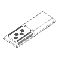
5.2 REMOVING EVAPORATOR COVER
To remove the evaporator cover do the following:
1. Turn all the 1/4 turn cam locks counterclockwise.
2. Using two people carefully grasp the cover under the
bottom edge and lift up.
3. Place the evaporator cover on top of the condenser
section.
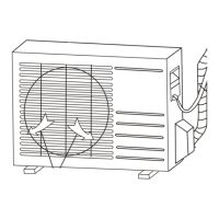
5.3 REMOVING CONDENSER COVER
To remove the condenser cover do the following:
1. Turn all the 1/4 turn cam locks counterclockwise.
2. Using two people carefully grasp the cover under the
bottom edge and lift up.
3. Place the condenser cover on top of the evaporator
section.
5.4 INSTALLING MANIFOLD GAUGE SET
A manifold gauge set can be used to determine system
operating pressures, add charge, equalize or evacuate
system.
When the suction pressure hand valve is frontseated
(turnedalltheway in), thesuction (low) pressure canbe
read. When the discharge pressure hand valve is
frontseated, discharge (high) pressure can be read.
When both valves are open (turned counterclockwise),
high pressure vapor will flow into the low side. When
only the low pressure valve is open, the system can be
charged or evacuated.
 Loading...