6
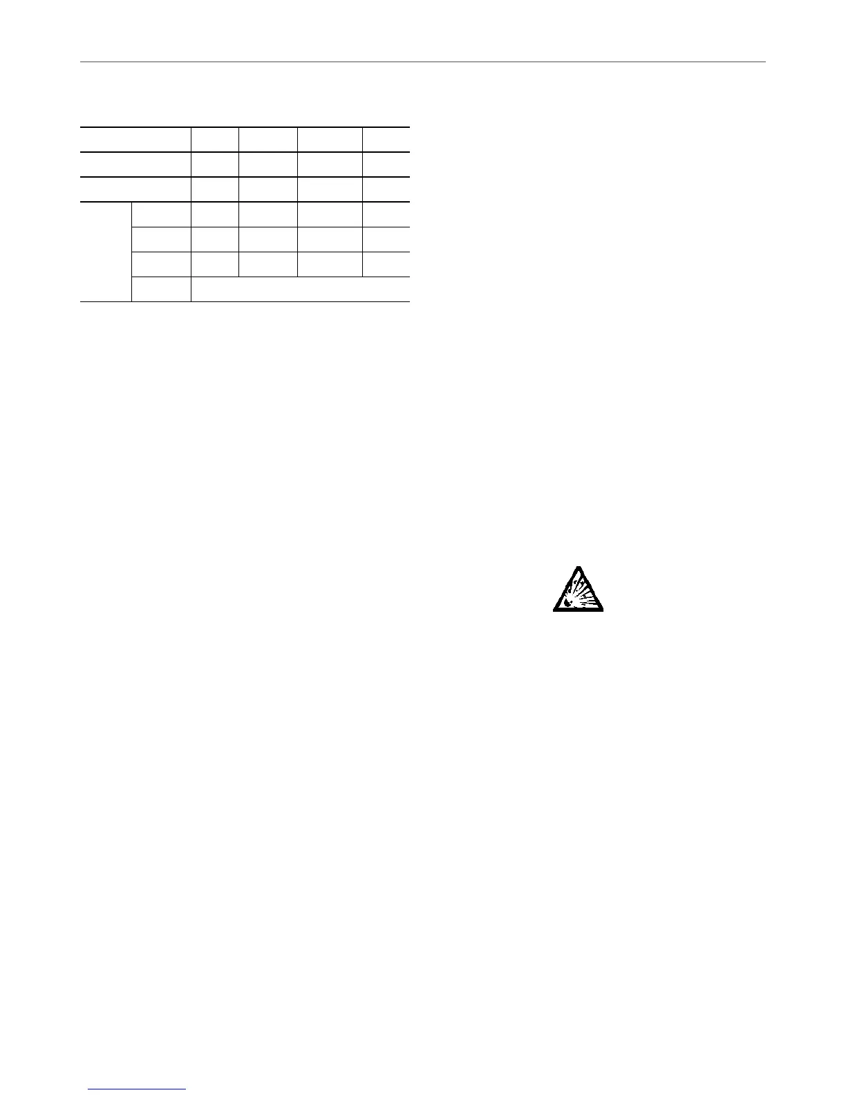
7. Periodic leak tests have to be carried out by the customer
or by third parties. The EU regulation set the periodicity
here after:
System WITHOUT
leakage detection
No Check 12 Months 6 Months 3 Months
System WITH leakage
detection
No Check 24 Months 12 Months 6 Months
Refrigerant charge/
circuit (CO
2
equivalent)
< 5 Tons
5 ≤ Charge
< 50 Tons
50 ≤ Charge
< 500 Tons
Charge >
500 Tons*
Refrigerant charge/
Circuit (kg)
R134A
(GWP 1430)
Charge
< 3.5 kg
3.5 ≤ Charge
< 34.9 kg
34.9 ≤ Charge
< 349.7 kg
Charge >
349.7 kg
R407C
(GWP 1774)
Charge
< 2.8 kg
2.8 ≤ Charge
< 28.2 kg
28.2 ≤ Charge
< 281.9 kg
Charge >
281.9 kg
R410A
(GWP 2088)
Charge
< 2.4 kg
2.4 ≤ Charge
< 23.9 kg
23.9 ≤ Charge
< 239.5 kg
Charge >
239.5 kg
HFO’s:
R1234ze
No requirement
* From 01/01/2017, units must be equipped with a leakage detection system
8.
A logbook must be established for equipments subject to
periodic leak tests. It should contain the quantity and the type
ofuidpresentwithintheinstallation(addedandrecovered),
thequantityofrecycleduid,regeneratedordestroyed,the
date and output of the leak test, the designation of the operator
and its belonging company, etc.
9. Contact your local dealer or installer if you have any
questions.
The information on operating inspections given in annex C
of standard EN 378 can be used if no similar criteria exist in
the national regulations.
While working in the fan area, especially when grilles or
casings are removed, disconnect the fan power supply to
prevent their automatic restart.
PROTECTION DEVICE CHECKS:
- If no national regulations exist, check the protection
devices on site in accordance with standard EN 378:
Once a year for the high-pressure switches, every
ve years for external relief valves.
The company or organisation that conducts a pressure switch test
must establish and implement detailed procedures for:
- Safety measures
- Measuring equipment calibration
- Validating operation of protective devices
- Test protocols
- Recommissioning of the equipment.
Consult Carrier Service for this type of test. Carrier mentions here
only the principle of a test without removing the pressure switch:
- Verify and record the set-points of pressure switches and
relief devices (valves and possible rupture discs)
- Be ready to switch-off the main disconnect switch of the
power supply if the pressure switch does not trigger (avoid
over-pressure or excess gas in case of valves on the
high-pressure side with the recovery condensers)
- Connect a pressure gauge protected against pulsations
(filled with oil with maximum pointer if mechanical),
preferably calibrated (the values displayed on the user
interface may be inaccurate in an instant reading because
of the scanning delay applied in the control)
- Complete an HP Test as provided by the software (refer
to the Control IOM for details).
If the machine operates in a corrosive environment, inspect
the protection devices more frequently.
Regularly carry out leak tests and immediately repair any
leaks. Ensure regularly that the vibration levels remain
acceptable and close to those at the initial unit start-up.
Before opening a refrigerant circuit, purge and consult the
pressure gauges.
Change the refrigerant after an equipment failure, following
a procedure such as the one described in NF E29-795 or carry
out a refrigerant analysis in a specialist laboratory.
Plug all openings whenever the refrigerant circuit is opened
for up to one day. For longer openings place a nitrogen charge
in the circuit.
1.4 - Repair safety considerations
All installation parts must be maintained by the personnel in charge,
in order to avoid material deterioration and injuries to people. Faults
and leaks must be repaired immediately. The authorized technician
must have the responsibility to repair the fault immediately. After
each repair of the unit, check the operation of the protection devices
and create a report of the parameter operation at 100%.
Comply with the regulations and recommendations in unit and
HVAC installation safety standards, such as: EN 378, ISO 5149,
etc.
If a leak occurs or if the refrigerant becomes contaminated (e.g.
by a short circuit in a motor) remove the complete charge using
a recovery unit and store the refrigerant in mobile containers.
Repair the leak detected and recharge the circuit with the total
R-134a charge, as indicated on the unit name plate. Certain parts
of the circuit can be isolated. Only charge liquid refrigerant R-134a
at the liquid line.
Ensure that you are using the correct refrigerant type before
recharging the unit. Charging any refrigerant other than the
original charge type (R-134a) will impair machine operation and
even destroy the compressors. The compressors operating with this
refrigerant type are lubricated with a synthetic polyolester oil.
RISK OF EXPLOSION:
Never use air or a gas containing oxygen during leak tests to
purge lines or to pressurise a machine. Pressurised air
mixtures or gases containing oxygen can be the cause of an
explosion.
Only use dry nitrogen for leak tests, possibly with an
appropriate tracer gas.
If the recommendations above are not observed, this can
have serious or even fatal consequences and damage the
installation.
Never exceed the specied maximum operating pressures.
Verify the allowable maximum high- and low-side test
pressures by checking the instructions in this manual and
the pressures given on the unit name plate.
Do not unweld or flamecut the refrigerant lines or any
refrigerant circuit component until all refrigerant (liquid and
vapour) as well as the oil have been removed from chiller.
Traces of vapour should be displaced with dry air nitrogen.
Refrigerant in contact with an open ame produces toxic
gases.
The necessary protection equipment must be available, and
appropriate fire extinguishers for the system and the
refrigerant type used must be within easy reach.
Do not siphon refrigerant.
1 - INTRODUCTION

 Loading...


