4
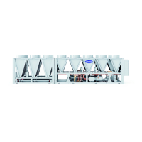
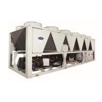
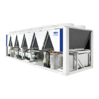
Table 1 — Unit Sizes
Conventions Used in This Manual — The follow-
ing conventions for discussing configuration points for the
Touch Pilot display will be used in this manual.
The menu items are shown in this document as they appear
on the Touch Pilot display. A path name for each item will
show the user how to navigate through the Touch Pilot display
to reach the desired configuration. The arrow symbol () in
the path name represents touching the menu item on the screen
of the Touch Pilot
™
display. See Appendix A for a complete
list of Touch Pilot menu items and descriptions.
The CCN and BACnet* point names are shown in bold.
See Appendix B for a list of CCN points, and Appendix D for a
list of BACnet points.
Abbreviations Used in This Manual — The fol-
lowing abbreviations are used in this manual:
• ABV — Actuated ball valve
• AUX — Auxiliary (Board)
• BACnet — Building Automation and Controls Network.
Open Protocol for the controlled exchange of data between
two or more intelligent control devices or BMS. BACnet is
used over IP (Internet Protocol).
• CCN — Carrier Comfort Network
®
. Protocol for the con-
trolled exchange of data between two or more intelligent
PIC (Peripheral Interface Controller)/FID (Field Interface
Device) devices within the geographic confines of a single
building.
• CWFS — Chilled water flow switch
• DGT — Discharge gas temperature
• DPT — Discharge pressure
• EMM — Energy Management Module
• EWT — Entering water temperature
• HMI — Human Machine Interface
• LEN — Local Equipment Network. Protocol for the con-
trolled exchange of data between two or more intelligent
control devices within the geographic confines of a single
Carrier equipment installation.
• LPT — Liquid pressure transducer
• LWT — Leaving water temperature
• OAT — Outdoor air temperature
• SCT — Saturated condensing temperature
• SDT — Saturated discharge temperature
• SLT — Saturated liquid temperature
• SIOB — Standard Input/Output Board
• SM — System Manager
• SPT — Suction pressure transducer
• SST — Saturated suction temperature
CONTROLS
The 30XV air-cooled liquid chillers contain the Touch Pilot™
electronic control system that controls and monitors all opera-
tions of the chiller. The control system is composed of several
components as listed in the following sections. All machines
have a Touch Pilot module, Standard Input/Output (SIOB)
boards, Emergency On/Off switch, and an Enable-Off-Remote
Contact switch. Table 2 lists power schematics by unit size.
Touch Pilot Display — The Touch Pilot module is the
core of the control system. It contains the major portion of
operating software and controls the operation of the machine.
See Web and Network Interface section on page 11.
The Touch Pilot module continuously monitors input/output
channel information received from the SIOB and AUX boards.
The Touch Pilot receives inputs from status and feedback
switches, pressure transducers and thermistors. The Touch Pi-
lot module, through the communications bus, also controls out-
puts on the SIOB and AUX boards. All inputs and outputs that
control the chiller are located on other boards. Information is
transmitted between modules via a 3-wire communication bus
or LEN (Local Equipment Network).
The CCN (Carrier Comfort Network
®
) bus is also supported.
Connections to both LEN and CCN buses are made at ter-
minal board TB3 located within the control box enclosure to
the left of the Touch Pilot display.
Touch Pilot Display User Interface — The Touch
Pilot display is the standard user interface on all 30XV
chillers with Greenspeed
®
intelligence. The display includes
a large 7-in. LCD (liquid crystal display) touch screen for
display and user configuration. A stylus is recommended for
use on the touch screen. The stylus is included with the unit.
WELCOME SCREEN — The Welcome screen is the first
screen shown after Touch Pilot starts. It displays the application
name as well as the current software version number. See Fig. 1.
NOTE: If a communication failure occurs, the Touch Pilot Set-
tings button is displayed (see the "Touch Pilot Display Port
Connections" table on page 11 and the "Touch Pilot Display
Interface and Connectors" figure on page 11 ).
To exit the Welcome screen, press the Home button .
HOME SCREEN — The Home screen provides an overview
of system controls, allowing the user to monitor the vapor-
refrigeration cycle. The screen indicates the current status of
the unit, giving information on the unit capacity, refrigerant
conditions, the status of the evaporator pumps, the active set
point, and other information. See Fig. 2.
UNIT NOMINAL CAPACITY (TONS)
30XV140 140
30XV160 160
30XV180 180
30XV200 200
30XV225 225
30XV250 250
30XV275 275
30XV300 300
30XV325 325
*BACnet is a registered trademark of ASHRAE (American Society of
Heating, Refrigerating, and Air-Conditioning Engineers).

 Loading...


