GB - 4
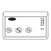
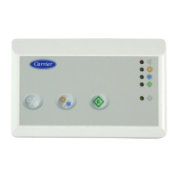
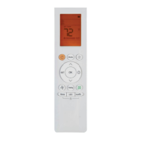
AQUASMART Room Controller
Electrical connections
Wiring Room Controller to the unit
WARNING:
Before connecting any wiring to the Room Controller,
turn off all power to the unit that will supply power to the
Room Controller.
Electrical shock can cause personal injury or death.
The Room Controller is connected to the unit using the
following instructions.
Reference Diagram 1 or 2 when making these connections.
Power cable and communication connections Room
controller to the unit (3 conductor cable).
• Slacken the terminal screws P (DC Power), G (GROUND) and
C (SIGNAL), present on the rear base of the Room Controller.
- P (DC power)
- G (Ground)
- C (Signal)
• Make the connections on the terminal block of the Room
Controller as per diagram 1.
• Connect the other end of the cables to the terminal block of
the unit as per diagram 1.
• Power cable installation is now complete.
• Slacken the terminal screws P (DC Power), G (GROUND)
and C (SIGNAL), present on the rear base of the Room
Controller.
- P (DC power)
- G (Ground)
- C (Signal)
• Make the connections on the terminal block of the Room
Controller as per diagram 2.
• Connect the other end of the cables to the terminal block of
the unit as per diagram 2.
• Power cable installation is now complete.
Wiring Materials required
(supplied by installer)
• 1 small screwdriver
• 3 x 0,5 mm
2
multiple cables, double insulated.
Suggested type: H03VV-F.
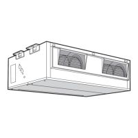
Diagram 2:
Connection diagram for the 42Y unit
Wire colours
A Brown
B Blue
Y/G Yellow/green
쐃 Room Controller
쐇 Unit
햴 Terminal block in the Room Controller
햵 Terminal block in the unit
햶 Window contact (if present)
햷 Local Bus; maximum 6 units
Diagram 1:
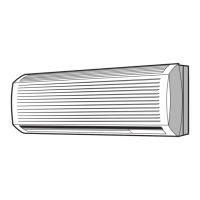
Connection diagram for the following units:
42GW
42WHC/WHE
42JW
42EL

 Loading...