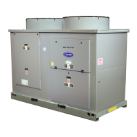
30RAP UNITS WITHOUT HYDRONIC PACKAGE (SIZE 060 SHOWN)
30RAP UNITS WITH HYDRONIC PACKAGE (SIZE 060 SHOWN)
NOTES:
1. Chiller must be installed level to within
1
/
8
in. per foot (10.4 mm per meter) to maintain proper compressor oil return and hydraulics.
2. Wiring and piping shown are general points-of-connection guides only and are not intended for a specific installation. Wiring and piping shown are
for a quick overview of system and are not in accordance with recognized standards.
3. All wiring must comply with applicable local and national codes.
4. All piping must follow standard piping techniques. Refer to Carrier System Design Manual or appropriate ASHRAE (American Society of Heating,
Refrigerating, and Air Conditioning Engineers) handbook for details.
LEGEND
Airflow Through Condenser
Power Wiring
Chilled Water Piping
LEGEND
Airflow Through Condenser
Power Wiring
Chilled Water Piping
NOTES:
1. Chiller must be installed level to within
1
/
8
in. per foot (10.4 mm per meter) to maintain proper compressor oil return and hydraulics.
2. Wiring and piping shown are general points-of-connection guides only and are not intended for a specific installation. Wiring and piping shown are for a
quick overview of system and are not in accordance with recognized standards.
3. All wiring must comply with applicable local and national codes.
4. All piping must follow standard piping techniques. Refer to Carrier System Design Manual or appropriate ASHRAE (American Society of Heating,
Refrigerating, and Air Conditioning Engineers) handbook for details.
5. Air separator required as close to chiller as possible (except primary/secondary systems).
a30-4869
a30-4870

 Loading...