26
3 - DIMENSIONS, CLEARANCES
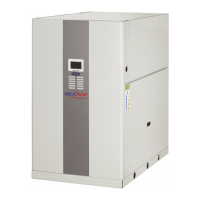
3.31 - 30WGA 150-190 - Standard unit
a
a
g
f
o
m
m
m
m
900 700
700700
884
897
1625 HT
1583
216
600
227
72
314
590242
239 325
51
1574
Option 70F main switch outside
3.32 - 30WGA 150-190 - Unit with hydraulic module (option 116)
a
g
f
a
o
m
m
m
m
325145
72
731255
720282
335312
51
900
700
700
2339
2381 HT
700
884
897
1574
Option 70F main switch outside
Legend
All dimensions are given in mm.
B
Evaporator
C
Condenser
D
Relief valve
E
Clearances required for maintenance (see note)
F
Control box
Water inlet
Power wiring connection
Power supply and control connection
NOTE: Non-contractual drawings. Refer to the certied
dimensional drawings available on request, when
designing an installation.
 Loading...

