2 - COMPOSITION
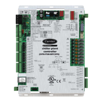
TERMINAL CCU Controller
J6
(SL)
1 Condensation unit 1 control
2
3 Refrigerating stage no. 1 common terminal
4 Condensation unit 2 control
5
6 Refrigerating stage no. 2 common terminal
J7
(SL)
1 Control of electric heater stage 1
2 Control of electric heater stage 2
3 Electric heater control common terminal
4 Supply air fan control
5 Not used
6 Fan control common terminal
J8
1 24 V AC power supply
2 24 V AC power supply
3 0 V
J9
1 RS485 A or + (Link between controllers for master/slave function)
2 RS485 B or - (Link between controllers for master/slave function)
3 0 V
J10
1 RS485 A or + (Link with CMS or gateway)
2 RS485 B or - (Link with CMS or gateway)
3 0 V
J14
1 + 12 V
2 RS485 A or + (Link with CPY humidier and/or FMA)
3 RS485 B or - (Link with CPY humidier and/or FMA)
4 0 V
J15
(SA)
1 0 V
2 Outdoor temperature sensor (10 K Ω)
3 Outdoor relative humidity sensor (0- 10 V)
4 Raised oor differential pressure monitoring sensor (0- 10 V)
5
Fan differential pressure sensor (0-10 V) or target temperature sensor (2-10 V) or percentage required
on external signal (2-10 V)
6 5 V
COM SWITCH
- COM 1: line termination resistance on CMS link (see section 13)
- COM 2: BUS polarisation on master/slave link (see section 12)
46
 Loading...