Do you have a question about the Carrier Crystal Plus 38KHFT24-708 and is the answer not in the manual?
| Brand | Carrier |
|---|---|
| Model | Crystal Plus 38KHFT24-708 |
| Category | Air Conditioner |
| Language | English |
Highlights critical safety measures, potential hazards, and conditions not covered by the manufacturer's warranty.
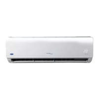
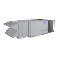
Illustrates and labels the key components of the indoor and outdoor units of the split system.
Details the model naming conventions and available system types (Heat Pump, Cool Only).
Specifies acceptable indoor and outdoor temperature ranges for optimal cooling and heating performance.
Outlines the nominal voltage, minimum, and maximum voltage for the air conditioner's power supply.
Provides detailed measurements (W, H, D) and weight for various indoor unit models.
Offers detailed dimensions (A, B, C, D, E) and weight for different outdoor unit models.
Guides on choosing the best location for the indoor unit, focusing on clearances, airflow, and accessibility.
Details factors to consider when selecting an outdoor unit location to ensure optimal performance and longevity.
Specifies required clearances around a single outdoor unit for proper airflow and maintenance access.
Provides clearance guidelines for serial installations of multiple outdoor units to prevent interference.
A checklist to verify proper installation site selection for both indoor and outdoor units, and piping.
Lists accessories included with the unit for domestic and export markets, such as remote controls and mounting hardware.
Details additional accessories not supplied by the factory but necessary for completing the installation.
A visual guide detailing the sequence of steps for installing the air conditioning system.
Outlines preliminary steps, including selecting the wall hole location for the indoor unit.
Provides detailed instructions for mounting the indoor unit, including bracket installation and cable management.
Step-by-step guide on installing batteries into the wireless remote control for operation.
Instructions on proper operation of the remote control, including aiming, distance, and avoiding interference.
Covers unpacking, preparation, and assembly of the wall support bracket for the outdoor unit.
A visual flowchart illustrating the key steps involved in connecting refrigerant piping lines.
Shows the four possible paths for refrigerant piping to exit the indoor unit.
Provides guidelines and recommendations for correctly connecting refrigerant piping to ensure performance and avoid damage.
Illustrates scenarios for piping line length (L) and vertical distance (H) based on unit placement.
Details the connection points and valves on the outdoor unit for refrigerant lines.
Shows the connection points for refrigerant piping on the indoor unit.
Lists the essential tools required for preparing refrigerant piping lines.
Provides specifications for gas and liquid line diameters and maximum allowable lengths.
Explains the factory refrigerant charge and how to add refrigerant for longer piping lengths.
Details initial steps for preparing refrigerant piping, including cutting and removing protective caps.
Continues the preparation steps, focusing on mounting flare nuts onto the piping ends.
Describes the process of connecting gas and liquid lines to the indoor unit half unions.
Details the procedure for connecting refrigerant lines to the flare valves of the outdoor unit.
Explains the importance of air purging and the procedure using the system's refrigerant.
Provides instructions for using a vacuum pump to purge air from the system.
Details the process of collecting refrigerant into the outdoor unit before disconnection or repair.
Describes methods for checking refrigerant leaks, including soapy water and leak detectors.
Guides on insulating piping to prevent condensation and conserve energy, including material thickness and application.
Specifies the required size of the drain line and its possible routing from the indoor unit.
Provides essential instructions for installing the drain line to ensure proper water drainage and avoid issues.
Details the electrical wiring requirements between the power supply, distribution box, and circuit breaker.
Covers wiring between indoor, outdoor units, and the main power supply, emphasizing safety and correct connections.
Presents electrical specifications, including consumption data and important notes on starting current and operating conditions.
Outlines preparatory steps for connecting electrical cables to the outdoor unit's terminal block.
Illustrates the specific electrical wiring diagram for the outdoor unit of a heat pump system.
Shows the electrical wiring diagram for the indoor unit of a heat pump system.
Provides wiring diagrams for connecting cool-only and heat pump systems (12K-18K) to power.
Details the wiring diagrams for 24K cool-only and heat pump systems connecting to the power supply.
Covers final steps like tidying cables, sealing wall holes, testing controls, and adjusting airflow.
Lists essential checks to perform before starting the unit's test run.
Explains how to perform a cooling test using the indoor unit's manual control button.
Details the process for conducting a cooling test, including checking pressures and amp consumption.
Outlines the process for performing a heating test, including measuring high pressure and total amps.
Explains how air is supplied and returned, and the importance of unobstructed flow.
Describes how the unit automatically adjusts vertical air direction based on operating mode.
Details how to use the swing function to automatically adjust horizontal louvers for air distribution.
Provides instructions for manually setting the horizontal louvers and cautions regarding their operation.
Verifies the correct installation and mounting of both indoor and outdoor units and their supports.
Confirms proper refrigerant piping, drain line, and electrical connections are made.
Ensures proper installation finishing, successful test runs, and customer guidance is completed.
Explains how the unit detects malfunctions in cool-only models and displays status via LEDs.
Details the self-diagnostic function for heat pump models, including LED indicators for various malfunctions.