40
Step 7 — Refrigerant Charge
NOTE: The liquid charging method is recommended for
complete charging or when additional charge is required.
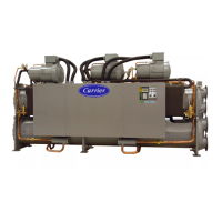
30HXC UNITS — The 30HXC units are shipped from the
factory with a full charge of R-134a. Unit should not need
to be charged at installation unless a leak was detected in
Step 6 — Leak Test Unit section. If dehydration and recharging
is necessary, use industry standard practices or refer to Stan-
dard Services Techniques Manual or the Controls, Start-Up,
Operation, Service, and Troubleshooting Guide as required.
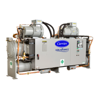
30HXA UNITS — The 30HXA units are shipped with a
holding charge of R-134a or nitrogen. The complete charge for
the 30HXA, the remote condenser(s), and interconnecting
piping must be field supplied.
To charge the 30HXA systems:
1. An initial refrigerant charge must be added after
evacuation to allow the unit to start. Add approximately
2 lb per nominal ton (0.26 kg per nominal kW) liquid re-
frigerant charge to the condenser. This amount of charge
should be sufficient to allow the unit to start. The cooler
refrigerant capacity is shown in Tables 8 and 9, approxi-
mate system charge is shown in Table 10.
2. Raise the compressor discharge pressure to approximate-
ly 185 psig (1276 kPa) (125 F [51.7 C] saturated con-
densing temperature) by throttling the condenser air (or
water) intake.
3. Add liquid charge into the cooler until there is approxi-
mately 18 to 20 F (10.0 to 11.1 C) of system subcooling
(saturated condensing temperature minus actual liquid
line temperature entering the electronic expansion valve
[EXV]). When adding charge, use the
1
/
4
-in. Schrader-
type fitting located on the tube going into the bottom of
the cooler. This fitting is located between the EXV and
the cooler.
4. Check for a clear sight glass. If the unit is not fully
loaded, the sight glass may be flashing. This condition is
normal for a partially loaded unit. If the unit is fully
loaded and the sight glass is flashing, check EXV posi-
tion. If it is greater than 60% add additional charge.
Table 8 — Cooler Refrigerant Storage Capacity
Table 9 — Fluid Weight of Refrigerant
in Liquid Line
NOTE: For refrigerant line lengths other than 25 ft (7.6 m), calculate
the total refrigerant charge by multiplying the liquid line length (in
feet) by the factor shown in this table and adding it to the cooler and
condenser charge listed in Table 10. Additional charge may be
required for the liquid line filter drier. Consult the manufacturer for
refrigerant charge information.
IMPORTANT: These units are designed for use with
R-134a only. DO NOT USE ANY OTHER REFRIGER-
ANT in these units without first consulting your Carrier
representative.
CAUTION
When charging, circulate water through the condenser and
cooler at all times to prevent freezing. Freezing damage is
considered abuse and may void the warranty.
CAUTION
DO NOT OVERCHARGE system. Overcharging results
in higher discharge pressure with higher cooling fluid
consumption, possible compressor damage, and higher
power consumption.
UNIT SIZE
30HXA
CKT
TOTAL
VOLUME
REFRIGERANT
STORAGE
CAPACITY
(R-134a)
Ft
3
m
3
lb kg
076,086
A 2.538 0.072 161 73.0
B 2.538 0.072 161 73.0
096
A 2.813 0.080 178 80.7
B 1.929 0.055 122 55.3
106
A 3.945 0.112 250 113.4
B 2.705 0.077 172 78.0
116,126
A 4.044 0.115 256 116.1
B 2.810 0.080 178 80.7
136,146
A 3.777 0.107 240 108.9
B 2.625 0.074 167 75.8
161
A 5.297 0.150 336 152.4
B 3.682 0.104 234 106.1
171
A 4.490 0.127 285 129.3
B 4.490 0.127 285 129.3
186
A 4.068 0.115 258 117.0
B 4.068 0.115 258 117.3
206
A 7.523 0.213 477 216.4
B 4.946 0.140 314 142.4
246-271
A 7.090 0.201 450 204.1
B 4.661 0.132 296 134.3
PIPING SIZE
(in.)
REFRIGERANT (lb)
PER FT OF TUBING
LENGTH
REFRIGERANT (kg)
PER M OF TUBING
LENGTH
1
1
/
8
0.41 0.61
1
3
/
8
0.63 0.94
1
5
/
8
0.89 1.33
2
1
/
8
1.52 2.26
 Loading...

