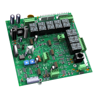
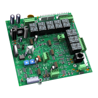
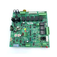
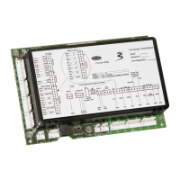
Communications wiring
Fan Coil CARRIER CORPORATION ©2020
Integration Guide All rights reserved
10
Wire specifications
○ A dedicated 22 AWG shielded twisted pair wire (EIA 485)
○ Maximum wire length 2000 feet (610 meters) or 32 nodes
○ Devices should be daisy-chained and not star-wired
○ Attach the drain/shield wire to both ends of the network segment and through every controller
NOTE Use the same polarity throughout the network segment.
6 Turn on the power for the Fan Coil by connecting power terminals.
Troubleshooting ARC156 communication
The most common communication problems result from not properly following the configuration steps outlined
above in this manual. Review all of the steps and use the following list to check your settings.
Verify accuracy of the following:
• Protocol DIP switches 3 and 4
• Proper connection wiring
• Unique rotary address switches 1 – 99. If controllers have duplicate addresses, network communication can
be lost.
• Unique BACnet Device Instance numbers. Default is 16101XX, with the rotary address switches defining XX. If
controllers have duplicate device instance numbers, network communication can be lost.
NOTES
• The controller recognizes physical changes (DIP switches, rotary switches, and jumpers) upon power up.
• If RX LED is solid, then the terminations are incorrect.
• If the network has greater than 32 devices or exceeds 2,000 feet, a Repeater should be installed.
• If a controller begins or ends a network segment, a terminating resistor may be needed.
Software settings defined through the Equipment Touch device. To confirm settings, obtain a Modstat of the
device. On the Equipment Touch, click the link to the Modstat.

 Loading...

