PGD4, PGS4, Series G, H WPG4 Series D, H Ultra Low NOx: Installation Instructions
Manufacturer reserves the right to change, at any time, specifications and designs without notice and without obligations.
2
Introduction
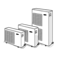
This unit (see Fig. 1) is a fully self-contained, combination Category I
gas heating/electric cooling unit designed for outdoor installation (See
Fig. 3 - Fig. 6 for unit dimensions). All unit sizes have return and
discharge openings for both horizontal and downflow configurations,
and are factory shipped with all downflow duct openings covered. Units
may be installed either on a rooftop or on a cement slab. (See Fig. 7 for
roof curb dimensions).
In gas heating mode, this unit is designed for a minimum continuous
return-air temperature of 55°F (13°C) db and a maximum continuous
return-air temperature of 80°F (27°C) db. Failure to follow these
return-air temperature limits may affect reliability of heat exchangers,
motors, and other components.
Models that start with a “P” that are ultra low NOx have a “2” in the 13
th
position, while models that start with a “W” have a “U” in the 11th
position. These models are dedicated to the Ultra Low NOx emissions
requirements of 14 nonograms/joule and must be installed in applicable
California Air Quality Management Districts or any other regions in
North America where Ultra Low NOx rule exists.
Receiving and Installation
Step 1 – Check Equipment
Identify Unit
The unit model number and serial number are stamped on the unit
information plate. Check this information against shipping papers.
Inspect Shipment
Inspect for shipping damage before removing packaging materials. If
unit appears to be damaged or is torn loose from its anchorage, have it
examined by transportation inspectors before removal. Forward claim
papers directly to transportation company. Manufacturer is not
responsible for any damage incurred in transit. Check all items against
shipping list. Immediately notify the nearest equipment distribution
office if any item is missing. To prevent loss or damage, leave all parts in
original packages until installation.
If the unit is to be mounted on a curb in a downflow application, review
Step 9 to determine which method is to be used to remove the downflow
panels before rigging and lifting into place. The panel removal process
may require the unit to be on the ground.
Step 2 – Provide Unit Support
For hurricane tie downs, contact distributor for details and PE
(Professional Engineering) Certificate if required.
Roof Curb
Install accessory roof curb in accordance with instructions shipped with
curb (See Fig. 7). Install insulation, cant strips, roofing, and flashing.
Ductwork must be attached to curb.
IMPORTANT: The gasketing of the unit to the roof curb is critical for a
water tight seal. Install gasketing material supplied with the roof curb.
Improperly applied gasketing also can result in air leaks and poor unit
performance.
Curb should be level to within 1/4 in. (6 mm). This is necessary for unit
drain to function properly. Refer to accessory roof curb installation
instructions for additional information as required.
Installation on older “G” series roof curbs.
Two accessory kits are available to aid in installing a new “G” series unit
on an old “G” roof curb.
1. Accessory kit number CPADCURB001A00, (small chassis) and
accessory kit number CPADCURB002A00, (large chassis) includes
roof curb adapter and gaskets for the perimeter seal and duct
openings. No additional modifications to the curb are required
when using this kit.
2. An alternative to the adapter curb is to modify the existing curb by
removing the outer horizontal flange and use accessory kit number
CPGSKTKIT001A00 which includes spacer blocks (for easy
alignment to existing curb) and gaskets for the perimeter seal and
duct openings. This kit is used when existing curb is modified by
removing outer horizontal flange.
Slab Mount
Place the unit on a solid, level pad that is at least 2 in. (51 mm) above
grade. The pad should extend approximately 2 in. (51 mm) beyond the
casing on all 4 sides of the unit. (See Fig. 2.) Do not secure the unit to
the pad except when required by local codes.
A07926
Fig. 2 – Slab Mounting Details
Step 3 – Field Fabricate Ductwork
Secure all ducts to roof curb and building structure on vertical discharge
units. Do not connect ductwork to unit. For horizontal applications, unit
is provided with flanges on the horizontal openings. All ductwork should
be secured to the flanges. Insulate and weatherproof all external
ductwork, joints, and roof openings with counter flashing and mastic in accordance with applicable codes.
CAUTION
!
FIRE, EXPLOSION, ELECTRICAL SHOCK AND
CARBON MONOXIDE POISONING HAZARD
Failure to follow this warning could result in personal injury or unit
damage.
A qualified installer or agency must use only factory-authorized kits or
accessories when modifying this product.
NOTICE
!
If the unit gasketing or insulation must be replaced, ensure the material
used is compliant with the two agency requirements listed.
1. Insulation and adhesives shall meet NFPA 90.1 requirements for
flame spread and smoke generation.
2. Cabinet insulation shall meet ASHRAE Standard 62.2.
CAUTION
!
UNITS/STRUCTURAL DAMAGE HAZARD
Failure to follow this caution may result in property damage.
Ensure there is sufficient clearance for saw blade when cutting the outer
horizontal flange of the roof curb so there is no damage to the roof or
flashing.
OPTIONAL
RETURN
AIR
OPENING
OPTIONAL
SUPPLY
AIR
OPENING
EVAP. COIL COND. COIL
ß
(50.8mm)
 Loading...