PGD4, PGS4, Series G, H WPG4 Series D, H Ultra Low NOx: Installation Instructions
Manufacturer reserves the right to change, at any time, specifications and designs without notice and without obligations.
32
done by removing the screws from the front cover of the burner box and
losing the screws on each side of the top cover to allow easy removal of
baffle from the burner box. Once the baffle is removed the inlet side of
the burner can be accessed and cleaned.
NOTE: This is NOT recommended to perform on yearly maintenance
inspections, only allowed for trouble shooting the burner box assembly
for any blockage.
NOTE: Burner/heat exchanger assembly
Due to the design, and to prevent damage to components, this is
considered as one assembly and cannot be disassembled. This assembly
is available to order though Replacement Components.
Outdoor Coil, Indoor Coil, and Condensate Drain Pan
Inspect the condenser coil, evaporator coil, and condensate drain pan at
least once each year.
The coils are easily cleaned when dry; therefore, inspect and clean the
coils either before or after each cooling season. Remove all obstructions,
including weeds and shrubs, that interfere with the airflow through the
condenser coil.
Straighten bent fins with a fin comb. If coated with dirt or lint, clean the
coils with a vacuum cleaner, using the soft brush attachment. Be careful
not to bend the fins. If coated with oil or grease, clean the coils with a
mild detergent and water solution. Rinse coils with clear water, using a
garden hose. Be careful not to splash water on motors, insulation, wiring,
or air filter(s). For best results, spray condenser coil fins from inside to
outside the unit. On units with an outer and inner condenser coil, be sure
to clean between the coils. Be sure to flush all dirt and debris from the
unit base.
Inspect the drain pan and condensate drain line when inspecting the
coils. Clean the drain pan and condensate drain by removing all foreign
matter from the pan. Flush the pan and drain trough with clear water. Do
not splash water on the insulation, motor, wiring, or air filter(s). If the
drain trough is restricted, clear it with a “plumbers snake” or similar
probe device.
A170032
Fig. 24 – Unit Access Panels
A200292
Fig. 25 – Removal of Motor and Blower Wheel
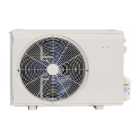
Outdoor Fan
1. Remove 6 screws holding outdoor grille and motor to top cover.
2. Turn motor/grille assembly upside down on top cover to expose fan
blade.
3. Inspect the fan blades for cracks or bends.
4. If fan needs to be removed, loosen set screw and slide fan off motor
shaft.
5. When replacing fan blade, position blade as shown in Fig. 26.
6. Ensure that set screw engages the flat area on the motor shaft when
tightening.
7. Replace grille.
WARNING
!
FIRE, EXPLOSION HAZARD
Failure to follow this warning could result in personal injury, death or
property damage.
Do not purge gas supply into the combustion chamber. Do not use a
match or other open flame to check for gas leaks.
Use a commercially available soap solution made specifically for the
detection of leaks to check all connections. A fire or explosion may
result causing property damage, personal injury or loss of life.
CAUTION
!
UNIT OPERATION HAZARD
Failure to follow this caution may result in damage to unit components.
Keep the condenser fan free from all obstructions to ensure proper
cooling operation. Never place articles on top of the unit.
COMPRESSOR
ACCESS PANEL
BLOWER
ACCESS
PANEL
CONTROL
ACCESS
PANEL
BLOWER
HOUSING
1 SET SCREW
(HIDDEN)
 Loading...

