INTRODUCTION
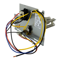
This instruction describes the installation of Part No. KFCEH accessory heaters in FA, FB, FC, FH, FX, and PF1MNB018-070 fan coils and in
the FE4, FK4, FV4, 40FK, and PF1MNA071 fan coils.
NOTE: Electric heaters require a minimum airflow. Minimum airflow and motor speed selection are listed in Table 2. For 3- through 18-kw
standard heaters there are no clearance requirements for the first 36 in. of ductwork. For 20- through 30-kw heaters, a 1-in. clearance is required
for the first 36 in. of ductwork.
INSTALLATION
PROCEDURE 1—INSTALL ELECTRIC HEATER ASSEMBLY
NOTE: Ensure heater coils are not deformed or damaged during heater installation.
1. Make sure power to unit is off.
2. Remove blower access panel of fan coil unit.
CAUTION:
Before installation of heater, the black and yellow pigtail leads must be removed from the fan coil PCB or
wire harness to prevent possible damage to the product. Electrical power will be provided to the board through the heater
circuit plug.
3. Disconnect 2 power wires (black and yellow pigtail leads) from PCB or wire harness (if applicable) and discard. Wires may be part of a
plug assembly or attached to terminals L1 and L2. Remove cooling control plate from fan coil (if equipped). For 18-, 24-, and 30-kw heaters,
remove adapter plate. (See Fig. 1.)
4. Insert heater assembly into front of fan coil so that element rods engage holes in rear heat shield.
5. Attach heater control plate to fan coil using 2 screws provided. For 18-, 24-, and 30-kw heater models, attach front of heater to fan deck
using third screw. (See Fig. 1.)
→ Table 1—Accessory Heater Usage
ELECTRIC HEATER
PART NO.
KW
INTERNAL
PROTECTION
MODEL FA, FB, PF
SIZE
MODEL FC
SIZE
MODEL FH
SIZE
MODEL FX
SIZE
MODEL
FE4, FK4, FV4, 40FK
SIZE
FK, FV, 40FK
INTELLIGENT
HEAT CAPABLE
1 Phase
KFCEH0401N03 3 Non-fused 018, 024 024 001 — — NO
KFCEH0501N05
KFCEH2401C05
5
Non-fused
Circuit Breaker
018-071 024-070 001-004 030-060 001-006
NO
NO
KFCEH0801N08
KFCEH2501C08
8
Non-fused
Circuit Breaker
018-071 024-070 001-004 030-060 001-006
NO
NO
KFCEH2901N09 9* Non-fused 036-071 036-070 002-004 036-060 003-006 YES†
KFCEH0901N10
KFCEH2601C10
10
Non-fused
Circuit Breaker
018-071 024-070 001-004 030-060 001-006
NO
NO
KFCEH3001F15
KFCEH2701C15
KFCEH3101C15
15
Fused
Circuit Breaker
Circuit Breaker
024-071 024-070 001-004 030-060 001-006
YES†
YES†
YES†
KFCEH3201F20
KFCEH2801C20
KFCEH3301C20
20
Fused
Circuit Breaker
Circuit Breaker
030-071 030-070 002-004 030-060 001-006
YES†
YES†
YES†
3 Phase Only
KFCEH1601315 15 Non-fused 036-071 036-070 002-004 036-060 001-006 NO
KFCEH2001318 18 Non-fused 042-071 042-070 003, 004 042-060 003-006 NO
3 Phase, Factory Shipped‡
KFCEH3401F24
KFCEH3501F30
24
30
Fused
Fused
048-071 048-070 003, 004 048-060 005, 006
YES†
YES†
† These heaters are Intelligent Heat capable when used with the FK4, FV4, and 40FK fan coils and corporate 2-speed programmable thermostat (TSTATXXP2S01-B),
Thermidistat™ Control (TSTATXXPRH01-B), or capable zoning system.
‡ Field convertible to 1 phase, single or multiple supply circuit.
* Field convertible to 3 phase.
Table 2—Minimum CFM and Motor Speed Selection
FAN COIL
SIZES
FA, FB, FC, FH, FX,
PF
HEATER KW
3 5 8 9 10 15 18 20 24 30
018 525 525 525 — 600* — — — — —
024 700 700 700 700 700 775* — — — —
030, 033 — 875 875 875 875 875 — 1060* — —
036, 038, — 1050 970 970 970 920 — 1040 — —
042 — 1225 1225 1225 1225 1225 1225 1225 — —
048, 054, — 1400 1400 1400 1400 1400 1400 1400 1400 1400
060, 070, — 1750 1750 1750 1750 1750 1750 1750 1750 1750
* Indicates medium speed (blue). All other motor speeds at low tap.
—2—

 Loading...