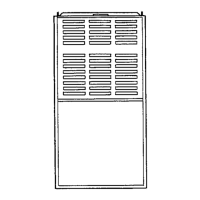
N95ESN: Installation, Start-up, Operating and Service and Maintenance Instructions
Manufacturer reserves the right to change, at any time, specifications and designs without notice and without obligations.
26
the HUM and COM/24V screw terminal on the control board thermostat
strip. See Fig. 36.
Alternate Power Supplies
This furnace is designed to operate on utility generated power which has
a smooth sinusoidal waveform. If the furnace is to be operated on a
generator or other alternate power supply, the alternate power supply
must produce a smooth sinusoidal waveform for compatibility with the
furnace electronics. The alternate power supply must generate the same
voltage, phase, and frequency (Hz) as shown in Table 10 or the furnace
rating plate.
Power from an alternate power supply that is non-sinusoidal may
damage the furnace electronics or cause erratic operation.
Contact the alternate power supply manufacturer for specifications and
details.
A11157
Fig. 36 – Field-Supplied Isolation Relay for Humidifiers with
Internal Power Supply
A190022
Fig. 37 – Example of Single Stage Furnace Control
A190085
Fig. 38 – Thermostat Wiring Diagrams
NOTES FOR THERMOSTAT WIRING DIAGRAMS
1. Refer to outdoor equipment Installation Instructions for additional
information and setup procedure.
2. Outdoor Air Temperature Sensor must be attached in all dual fuel
application.
3. Refer to ICP thermostat Installation Instructions for additional
information and setup procedure.
4. HUM 24VAC terminal is 24 VAC and is energized when the low
pressure switch closes during a call for heat.
5. When connecting 115 VAC to humidifier use a separate 115 VAC
supply.
6. When using a humidifier on a HP installation, connect humidifier to
hot water.
24 V
Coil
To Humidifier Leads
To Com/24V Screw Terminal
on Thermostat Strip
To HUM Terminal On
Furnace Control Board
To Humidifier Leads
24-V THERMOSTAT
TERMINALS
P2 – (115VAC) HOT SURFACE IGNITER &
INDUCER MOTOR 115V SUPPLY CONNECTOR
115-VAC (L2) NEUTRAL
CONNECTIONS
115-VAC (BL-1) BLOWER MOTOR LINE
VOLTAGE CONNECTION
EAC-1 TERMINAL
(115-VAC 1.0 AMP MAX.)
P1 – LOW VOLTAGE MAIN HARNESS
CONNECTOR
TRANSFORMER 24-VAC
CONNECTIONS
HUMIDIFIER TERMINAL
(24-VAC 0.5 AMP MAX.)
BOARD PART NUMBER
LOCATION
115-VAC (PR-1) TRANSFORMER
PRIMARY
HEAT OFF-DELAY
JUMPER SELECT
PLT -FACTORY RUN TEST PORT
PRODUCTION USE ONLY
115-VAC (L1) LINE VOLTAGE
CONNECTION
Single-Stage Furnace with Single-Speed Air Conditioner
Single-Stage Furnace with Single-Speed Heat Pump
THERMOSTAT
THERMOSTAT
*
*
D
D
See notes 1 and 4
See notes 1 and 3
 Loading...
