2-3
2.3.3 Heat Operation (See Figure 2-3.)
Thedriver’sA/CSwitch(ACS)isplacedintheHEAT
position to activate the heatingcycle. With this switchin
the HEAT position, 24-vdc is applied to energize Heat
Relay (HR) and Evaporator Speed Relays (ESR1 and
ESR2). Energizing the Heat Relay (HR) closes a set of
normallyopenHRcontacts,whichallows thethermostat
to energize Boost Pump Relay (BPR) and Reheat
Coolant Valve (RCV) upon a demand for heating.
Energizing Evaporator Speed R elays (ESR1 and ESR2)
opens normally open ESR1 and ESR2 contacts to start
lowspeedevaporatorfanoperationprovidedEvaporator
Fan Relay (EFR1) i s energized. Energizing Boost Pump
Relay (BPR)closes normallyopenBPRcontactstostart
Boost Pump Motor (BPM). Energizing Reheat Coolant
Valve(R CV)opensthevalveandstartstheflowofengine
coolant through the heating coils for heating.
Whenthe ACS switchis intheHeat position, power
isalsosuppliedtoRunC ontrolSwitch(RCS1).WithRun
ControlSwitches(RCS1 and RCS2) in the ON position,
power i s applied through the Run Control Switches to
energize Fault Relay (FR), Evaporator Fan Relay
(EFR1) and Low Voltage Cutout Relay (LVCO).
Energizing the Fault Relay closes a set of normally open
FR contacts in the cooling control circuit and, provided
there is no high or low pressure refrigerant condition,
opens the circuit to the stop light. The Low Voltage
Cutout Relay senses circuit control voltage and
de-energizes to open normally open LVCO contacts to
de-energize theClutchRelay(CR)duringcooling,when
a low voltage condition occurs.
When the vehicle interior temperature falls to -2˚F
below the thermostat setpoint, the thermostat switches
from low speed vent to low speed heat mode. (See
Figures2-3and2-9.)Inthismode,thethermostatapplies
powertoplugJ1,pinno.1,toenergizeBoostPumpRelay
(BPR) and Reheat Coolant Valve (RCV) through the
closed HR contacts. Energizing Boost Pump Relay
(BPR)closesnormallyopen BPRcontacts to startBoost
Pump Motor (BPM). Energizing Reheat Coolant Valve
opens the valve and starts the flow of engine coolant
through the heating coils. During the heating cycle, this
valve is opene d and closed and the pump is started and
stopped on thermostat command to control vehicle
interior temperature.
When the vehicle interior temperature rises to the
setpoint,thethermostat switches fromlow speedheatto
low speed vent mode. In this mode, the thermostat
removes power from plug J1, pin no. 1, which
de-energizes the Reheat Coolant Valve (RCV) and
Boost Pump Relay (BPR) to stop the flow of coolant to
the heating coils. The evaporator fans will continue to
operate on low speed to circulate air throughout the
vehicle.
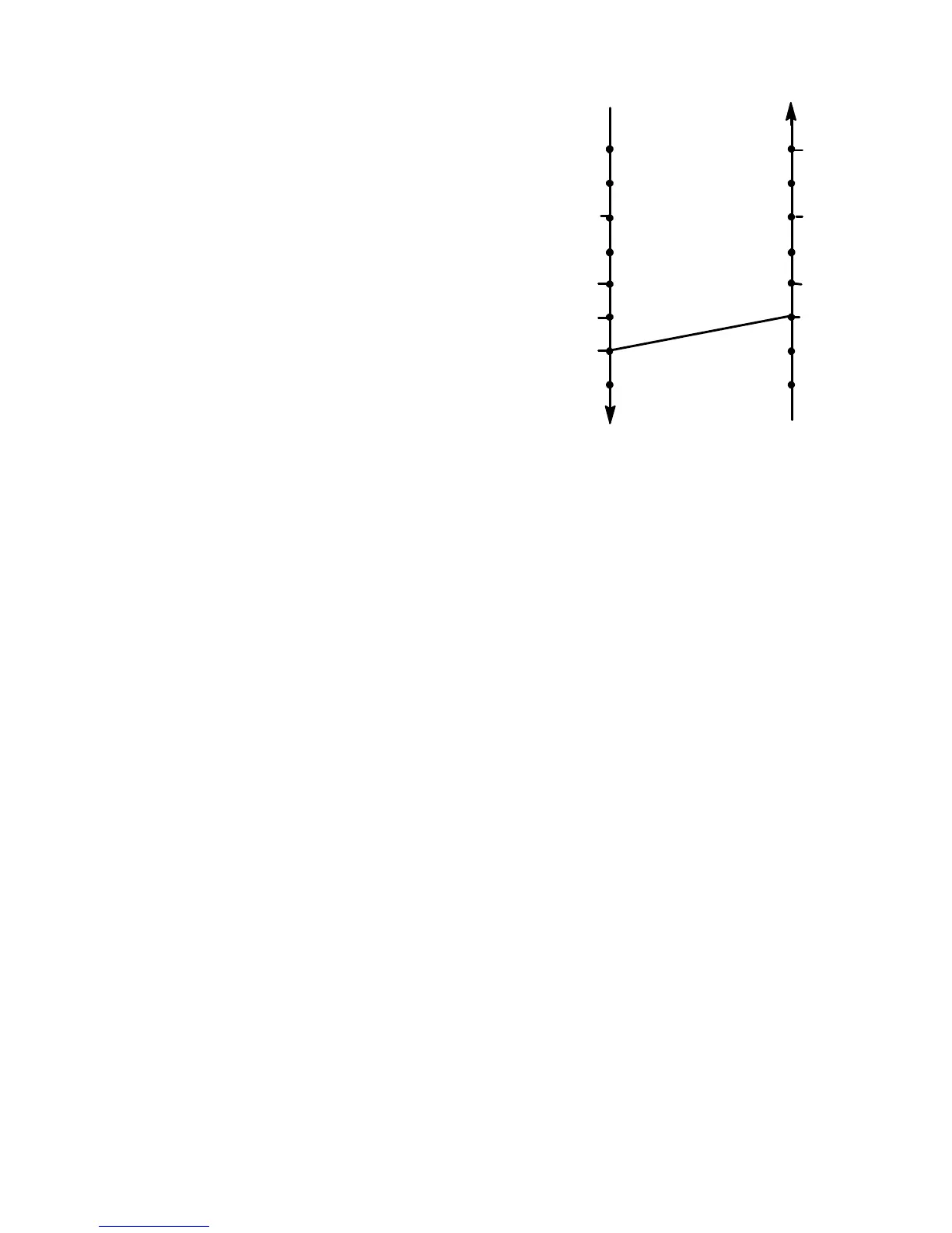
Fig ure 2-3. Temperatu re Controll er Sequence
During Heating Mode
FALLING
TEMPERATURE
1˚FABOVE
SETPOINT
SETPOINT
SETPOINT
3˚FABOVE
SETPOINT
LOW SPEED VENT
5˚FABOVE
SETPOINT
3˚FABOVE
SETPOINT
1˚FABOVE
SETPOINT
RISING
TEMPERATURE
LOW SPEED HEAT
-2˚FBELOW
SETPOINT

 Loading...