Caution:
• Improper tightening of bolts would lead to the faults shown in the following gure.
Air leakage
Ceiling
pollution
Water condensate, water dripping
Clearance is not allowed
• After tightening the bolts, if there is a clearance between the ceiling and the trim panel, please readjust the
height of the indoor unit.
Installation Procedures
• Install the two claws into the snap and secure with the screws. (Screw hole position as shown, hidden parts have been
hidden).
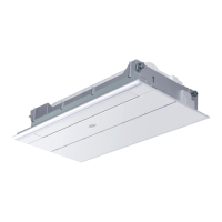
Decorative panels of the line
• Connect the connector on the right side of the trim panel to the stepped motor wire (10-pin)
• Connect the connector on the left side of the trim panel to the stepped motor wire (5-pin)
• Connect the connector of the lamp panel mounted on the trim panel (9-pin)
• Connect the communication cable, the power cord, and use the controller to check whether the connection is correct,
make sure the machine can be installed after the normal operation of the lter, the return air guide back.
claws
snap
right stepper motor
left stepper motor
function indicator
10
English
 Loading...
