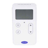
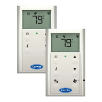
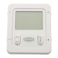
SPT Sensors
Carrier Sensors CARRIER CORPORATION ©2021
Installation Guide All rights reserved
19
5 Insert the other 4 wires into the sensor's screw terminal connector. If wiring 2 cables, insert like-colored wires
into each terminal.
Carrier recommends that you use the
following Rnet wiring scheme:
Connect this
wire...
Red
Black
White
Green
To this terminal...
+12V
Rnet-
Rnet+
Gnd
CAUTION Allow no more than .06 inch (1.5 mm) bare communication wire to protrude. If bare communication
wire contacts a metal surface other than the terminal block, the sensor may not communicate correctly.
6 Attach the sensor's cover and circuit board to the mounting plate, inserting the top first.
7 Turn the setscrew one full turn counterclockwise to secure the cover to the mounting plate.
8 Wire the sensor to the Open controller. See the controller's Installation and Startup Guide for details.
Downloaded from ManualsNet.com search engine

 Loading...