INSTALLATION
I. ASSEMBLY
1.
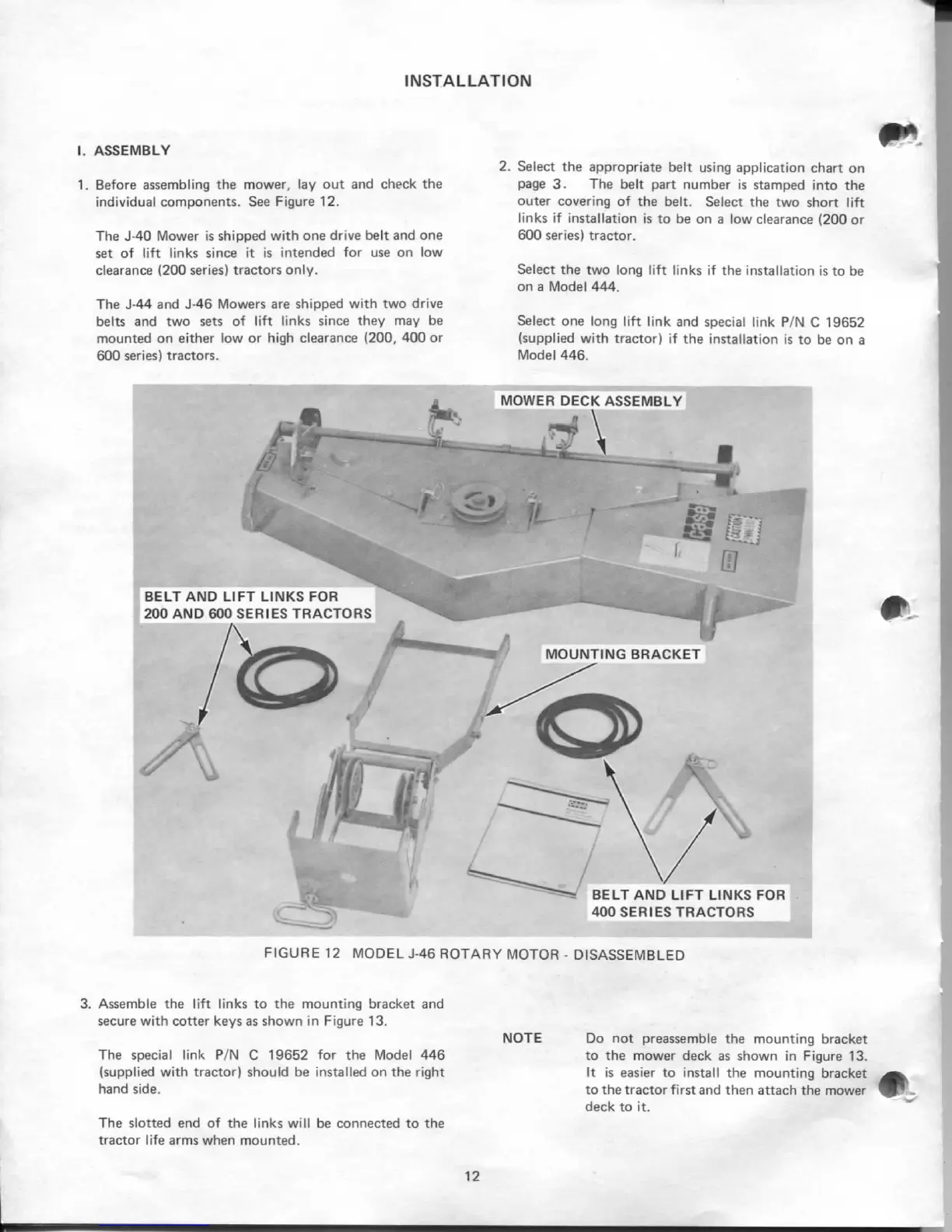
Before assembling the mower, lay out and check the
individual components. See Figure 12.
The J-40 Mower is shipped with one drive belt and one
set of lift links since it is intended for use on low
clearance (200 series) tractors only.
The J-44 and J-46 Mowers are shipped with two drive
belts and two sets of lift links since they may be
mounted on either low or high clearance {200, 400 or
600 series) tractors.
2.
Select the appropriate belt using application chart on
page 3. The belt part number is stamped into the
outer covering of the belt. Select the two short lift
links if installation is to be on a low clearance (200 or
600 series) tractor.
Select the two long lift links if the installation is to be
on a Model 444.
Select one long lift link and special link P/N C 19652
(supplied with tractor) if the installation is to be on a
Model 446.
FIGURE 12 MODEL J-46 ROTARY MOTOR - DISASSEMBLED
3. Assemble the lift links to the mounting bracket and
secure with cotter keys as shown in Figure 13.
The special link P/N C 19652 for the Model 446
(supplied with tractor) should be installed on the right
hand side.
The slotted end of the links will be connected to the
tractor life arms when mounted.
NOTE Do not preassemble the mounting bracket
to the mower deck as shown in Figure 13.
It is easier to install the mounting bracket
to the tractor first and then attach the mower
deck to it.
12
casecoltingersoll.com
 Loading...