EasyManua.ls Logo

Case Magnum 7220 User Manual

Case Magnum 7220
26 pages
To Next Page IconTo Next Page
Page #1 background imageLoading...
Page #1 background image
CASE
nir
Service
Bulletin
FILING INSTRUCTIONS
Binder: AG EQUIPMENT BINDER
Page: 1 of 26
Binder Section: AGRICULTURAL TRACTORS
Document No.: NTR SB 026 96
I
Mach
Loc
Code: 40000
Issued By:
PRODUCT MANAGEMENT,
RACINE,
WISCONSIN, USA
Family: Magnum
Model:
7210,7220,7230,7240,7250
Supersedes:
Date Issued: 1
1/20/96
Subject:
Magnum Hitch Diagnostic Codes and Service Manual Update
Background The following service bulletin will provide the dealer with more detailed troubleshooting
nformation on the Magnum 7200 series hitch system. The dealer should make a copy of this bulletin
and
place in section 4002 page 45 or section 8009 of the 7200 series Service Manual.
Note: The hitch calibration procedure is found in the 7200 series Service Manual section 8009
Of
Service Manual is no longer Correct.
Note:
The 7100 and 8900 series tractor require a different calibration procedure.
This
bulletin will cover the following items.
1.
General information
...............................................................................................
page
2
2.
General testing of the hitch system
........................................................................
Reading and erasing error codes
page
3
-
4
3.
...........................................................................
page
5
4.
Hitch performance codes (during field operations)
................................................. page
6
-
10
5.
7200 series hitch calibration procedure
.................................................................
page
11
-
12
6.
Hitch diagnostic codes (during calibration)
.............................................................
7.
Hitch diagnostics by problem..
page 13
-
14
........
....................................................................... page
15
-
16
8.
Hitch component function and troubleshooting
....................................................
- - page 17
-
18
9.
Hitch electrical component part numbers
...............................................................
page
19
10.. Eliminating load pins and draft control from the Magnum tractor
.........................
19
1
1. Testing rockshaft and position lever potentiometers
- - page
..............................................
20
12. Bench testing rockshaft and position lever potentiometers
page
....................................
20
13. Testing wiring harness at the 37 pin, 16 pin amp connector
page
.................................page 21
-
24
14.
Testing the EDC relay on tractors below serial number JJA0064978
....................
15. Testing hitch enable relay
page 25
.....................................................................................
page
25
16. Correction to wiring schematic found in section 4002 page 27
.............................page
26
SERVICE BULLETINS DO NOT CONSTITUTE WARRANTY AUTHORIZATION TO UPDATE UNITS
Question and Answer IconNeed help?

Do you have a question about the Case Magnum 7220 and is the answer not in the manual?

Case Magnum 7220 Specifications

General IconGeneral
TypeRow-Crop tractor
Engine TypeDiesel
TransmissionFull Power Shift
Hydraulic SystemClosed Center Pressure Flow Compensated (PFC)
PTO Speed540/1000 rpm
Fuel Tank Capacity100 gal
Width96 inches
Height118 inches
Tire OptionsVarious options available
Tire SizeFront: 420/85R34, Rear: 520/85R46
Engine6-cylinder turbocharged aftercooled diesel
Wheelbase116 inches

Summary

General Hitch System Testing

Reading and Erasing Error Codes

Electronic Hitch Diagnostic Codes

Hitch Control Module Failure Modes

Explains HALT, LIMP, DEGRADED 2, DEGRADED 1 modes.

Hitch System Failure Codes

HALT Mode Failure Codes

Codes H2, HU, H3, H9, HP, ], Hilb, Hh, HJ, Hd.

Hitch System Failure Codes (Continued)

LIMP Mode Failure Codes

Codes H, P, Γ, A, F, C, E, [ for LIMP mode.

Electronic Hitch Performance Codes

DEGRADED 1 Performance Codes

Codes U, 6, 7, 9, 4 for DEGRADED 1.

Electronic Hitch Performance Codes (Continued)

RAISE/LOWER and Sensor Failure Codes

Codes FP, FH for RAISE/LOWER & sensor issues.

7200 Series Hitch Calibration Procedure

Pre-Calibration Requirements

Ensure components are working and hitch is free.

Initial Calibration Steps

Install test box, center hitch, clear codes, set position pot.

Position Potentiometer Testing

Testing voltage range of position control lever.

Initiating Calibration Sequence

Starting engine and using hitch switch for calibration.

Hitch Calibration Procedure Continued

Upper Limit Knob Query

Responding to the upper limit knob query.

Hitch Lowering Sequence

Holding switch for hitch to lower completely.

Rockshaft Potentiometer Testing

Testing voltage range of rockshaft potentiometer.

Hitch Raising Sequence

Raising hitch and observing diagnostic display.

Hitch Diagnostic Codes During Calibration

Calibration Failure Types

System vs. component failures during calibration.

Troubleshooting Position Command Issues

Codes H.F, H.J, H.Γ, H.a related to position command.

Troubleshooting Raise PWM Issues

Codes H.U, H.J related to Raise PWM.

Hitch Diagnostic Codes During Calibration (Continued)

Troubleshooting Position Command Not Minimum

Codes H.4, H.Ξ for position command not at minimum.

Hitch Diagnostics by Problem

Hitch Diagnostics by Problem (Continued)

Hitch Leaks Down (Engine Off)

Isolating lift assist cylinders and testing rockshaft cylinder.

Hitch Leaks Down (Engine On)

Testing rockshaft cylinder and cushion relief valve.

Hitch Valve Components and Function

Hitch Valve Solenoid Operation

Solenoid plunger function and resistance specs.

Pilot Spool Operation

Pilot spool movement and effect on control spool.

Hitch Valve Components and Function (Continued)

Control Spool Operation

Control spool movement and hitch reaction.

Lockout Plunger Spool Operation

Lockout spool function and potential issues.

Eliminating Draft Control

Draft Control Elimination Procedure

Unplugging draft pins and reprogramming hitch controller.

Testing Rockshaft and Position Lever Potentiometers

Bench Testing Potentiometers

Testing Wiring Harness at 37 Pin Connector

Testing Wiring Harness at 37 Pin Connector (Continued)

Testing Wiring Harness at 16 Pin Connector

Testing Wiring Harness at 16 Pin Connector (Continued)

Testing Wiring Harness at EDC Relay #6

Correction to Wiring Schematic

Rockshaft Position Sensor Wiring Correction

Corrected wiring for the rockshaft position sensor.
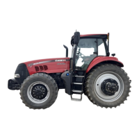
Related product manuals