— 14 —
IC17
UPD65611GB-019-3BA
LG
CPU
LSI14
HD6433294A33F
LVDD
P40
P41
LC1
LC8
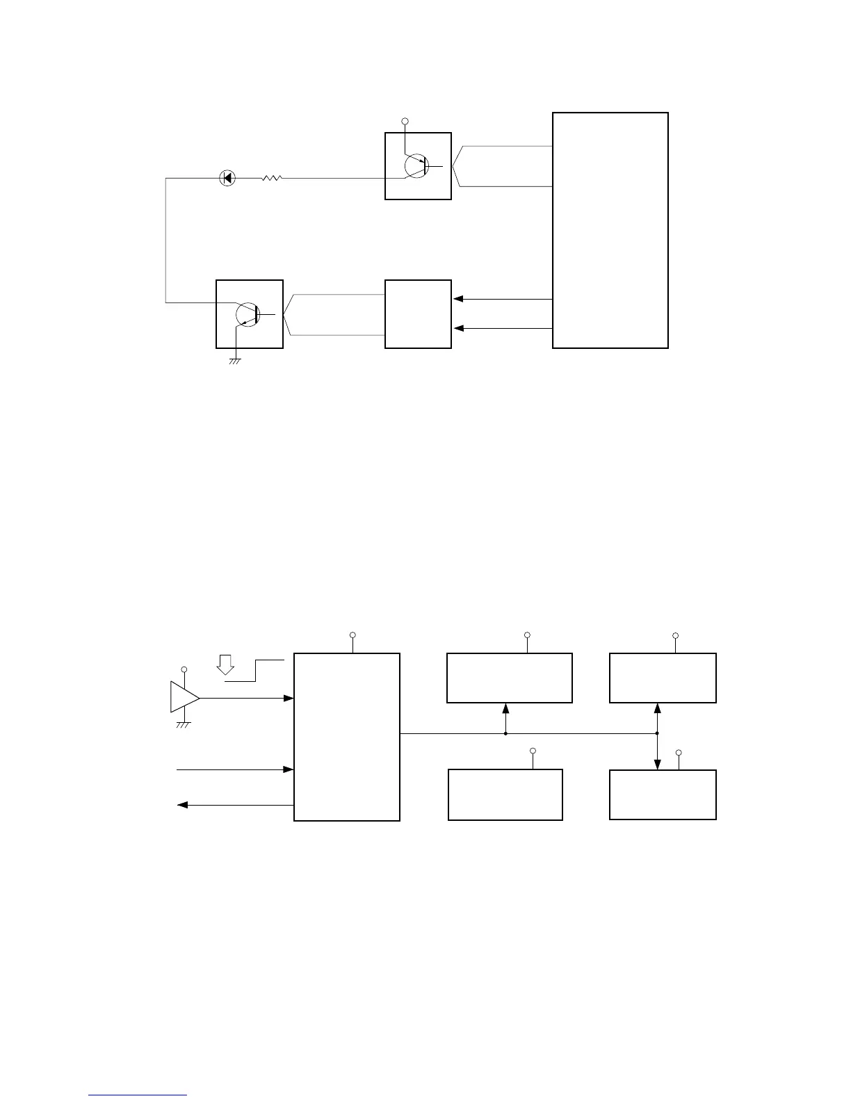
KO0 ~ KO3, KO5
IC301
BA612
LED Driver
Q15 ~ Q18
LED Driver
LD0 ~ LD7
La ~ Lg, Lp
Gate array
LED DRIVING
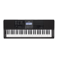
RESET CIRCUIT
When batteries are set or an AC adapter is connected, the reset IC provides a low pulse to the CPU. The CPU
then initializes its internal circuit.
When the power switch is pressed, the CPU receives a low pulse of POWER signal. The CPU provides APO
signal to the power supply circuit and raises RESET signal to +5 V to reset the DSP, the key controller and
the gate array.
VDD
Battery set
RESET
CPU
LSI14
HD6433294A33F
Reset IC
IC13
RH5VL36AA
Working Storage RAM
LSI15
TC55257DFL-70L
DSP
LSI11
HG51B155FD-1
Key Controller
LSI16
HG52E35P
DVDD
DVDD
DVDD
VDD
VDD
-RESET
POWER
From power switch
Gate Array
LSI17
UPD65611GB-019-3BA
-NMI
To power supply circuit
APO
P42