EasyManuals Logo

CASTLE PHOENIX EDGE ESC User Manual

CASTLE PHOENIX EDGE ESC
2 pages
To Next Page IconTo Next Page
Page #1 background imageLoading...
Page #1 background image
www.modellmarkt24.ch
EDGE ESC LOCK HARNESS AND KEY
Mounting
The socket my be
instlled through 
pnel or secured inside 
fuselge.
Wiring Diagram
Connect the white wire to the Aux Line (white wire) on
n Edge ESC.
Connect the red “+” wire to ny servo wire with  Y
hrness.
Warning
Edge Arm Lock mode is intended s 
secondry sfety device. It is not intended
to replce sfe prctices or creful hndling
of your RC power system, vehicle, nd
trnsmitter.
Edge Arm Lock is only opertionl if you
hve successfully configured the Edge ESC
using Cstle Link softwre.
Edge Arm Lock requires tht the AUX LIE
of the Edge ESC receives  voltge between
1.8V nd 8.4V to rm. Filure of the power
source (0 volts) will cuse the ESC to enter
Arm Lock mode.
Operation
Key in socket OR disconnected wire in socket hrness
= AR LOCKED.
A properly progrmmed nd wired Edge will be
incpble of rming when the key is in the socket.
If the key is plced in the socket or the rm lock socket
loses power, the ESC will go into  locked stte - even
if it is running.
Key removed + power to socket = AR ULOCKED. ESC
must receive low throttle signl to rm nd run.
www.modellmarkt24.ch

Questions and Answers:

Question and Answer IconNeed help?

Do you have a question about the CASTLE PHOENIX EDGE ESC and is the answer not in the manual?
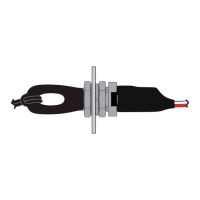
CASTLE PHOENIX EDGE ESC Specifications

General IconGeneral
BrandCASTLE
ModelPHOENIX EDGE ESC
CategoryLocks
LanguageEnglish