20
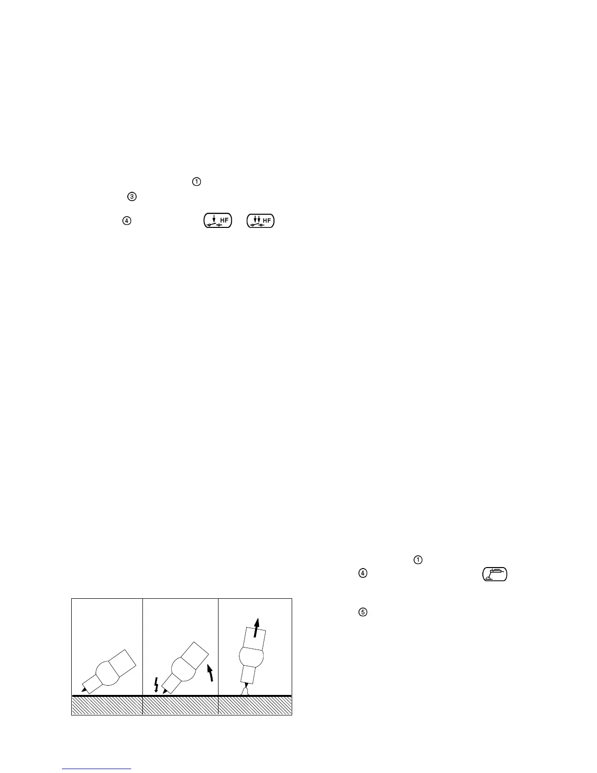
Fig. 8: Ignition assisted by HF.
a)Rest on gas nozzle
edge
b)Switch HF on c) Arc ignites
Arc ignition
o Prior to depressing th trigger, place the electrode tip
on the weld at the point where the arc is to be
ignited. Tilt the torch backwards until the edge of the
gas nozzle rests on the workpiece, and pursue until
a gap of 2 to 3 mm is obtained. Hold the position
(Fig. 8a).
o Protect your eyes with a welding helmet.
o Depress the trigger; the gas starts flowing and the
HF is on.
o The arc is lit without contact between the electrode
and the workpiece (Fig. 8b).
o Ensure a normal arc length (Fig. 8c).
Advantage: No mutual contamination, neither of
the electrode nor of the base metal.
Important: The HF is automatically switched off once
the arc column is established.
Ignition monitoring:
If, after an unsuccessful attempt to ignite the arc, or
after an arc interruption, the welder forgets to stop the
control sequence by the appropriate action on the torch
trigger (especially in 4-step mode), the shielding gas
would continue to flow, leading to considerable waste
of gas. To prevent this inconvenience, a monitoring
function automatically interrupts the control sequence
after approx. 1 second. Then a new attempt requires a
repetition of the ignition process with the torch trigger.
TIG wTIG w
TIG wTIG w
TIG w
elding in 2-steelding in 2-ste
elding in 2-steelding in 2-ste
elding in 2-ste
p modep mode
p modep mode
p mode
o Depress and hold the trigger forwards:
- Gas pre-flow (only with HF)
- Arc ignition
- Current increases up to the pre-set value
o Release the trigger:
- Current reduces down to the crater filler pre-set
value.
- Arc interrupted.
- Gas post-flow.
TIG wTIG w
TIG wTIG w
TIG w
elding in 4-steelding in 4-ste
elding in 4-steelding in 4-ste
elding in 4-ste
p modep mode
p modep mode
p mode
o Depress the trigger forwards and release it:
- Gas pre-flow (only with HF)
- Arc ignition
- Current increases up to the pre-set value.
o Depress again and hold the trigger forwards:
- Current decreases down to the crater filler pre-
set value.
- Arc maintained at low amp for filling up the
crater.
o Release the trigger:
- Arc interrupted.
- Gas post-flow.
ManMan
ManMan
Man
ual Metal ual Metal
ual Metal ual Metal
ual Metal
ArAr
ArAr
Ar
c c
c c
c
WW
WW
W
eldingelding
eldingelding
elding
Start up
o Select the polarity according to the coated stick
electrode in use.
o Plug the welding cable into the corresponding
socket and secure it by turning clockwise.
o Plug the mains cable in,
o Switch the main switch on
o Select by the corresponding process ; the
LED lights up and a welding current value appears
on the display.
o Adjust by the desired value.
o Proceed with welding.
Start up
o Fit the torch with a tungsten electrode and a gas
nozzle suitable for the application (see instruction
leaflet of the torch).
o Connect and lock the ground cable to the socket B.
o Connect the gas hose to the pressure reducer of the
gas supply.
o Plug in the mains plug.
o Switch on the main switch ,
¨ Select by the TIG or pulsed TIG process; the
LED lights up.
o Select by the control mode or the
LED lights up.
o Adjust the relevant welding parameters.
o Open the gas supply valve.
o Depress the trigger (and release it if 4-step mode).
WARNING! HF is on!
o Adjust the gas flow with the setting screw of the
pressure regulator.
o Release the trigger (depress and release it if 4-step
mode).
TIG welding with high-frequency
ignition (HF)
 Loading...