• the experience of personnel
Note: For more information on drying methods, refer
to Special Instruction, SEHS9124, “Cleaning and
Drying of Electric Set Generators”.
Remove the voltage regulator. Cover all of the inlet
openings. Cover all of the discharge holes. Provide
an opening at the top of the machine. This opening
will allow moisture to evaporate. Preferably, this
opening will be located at the fan end. Monitor the
winding temperatures. DO NOT APPLY HEAT TOO
RAPIDLY. Winding temperature should be raised
gradually at a rate of 10 °C (50 °F) per hour up to
85 °C (185 °F). Measure insulation resistance in 1
hour intervals. Typically, the insulation resistance will
slowly drop while the temperature is rising. The
insulation resistance will then start to increase at a
slow rate until the insulation resistance reaches a
constant level.
The following methods can be used for drying a
generator:
• Self-circulating air method
• Oven method
• Controlled current method
Self-Circulating Air Method
Run the engine and disconnect the generator load.
Running the engine will help circulate air. Operate the
generator space heaters.
Oven Method
Place the entire generator inside a forced air drying
oven for 4 hours at 65 °C (149 °F).
NOTICE
Use a forced air type oven rather than a radiant type
oven.
Radiant type ovens can cause localized overheating.
Controlled Current Method
Table 20
Tools Needed
Part Number Description Qty
225-8266
Ammeter Tool Gp 1
External Power Source 1
Rheostat 1
Heat can be used in order to dry the generator
windings. This heat can be created by allowing a
controlled current to flow through the generator. No
high voltages are generated during the following
procedure. Therefore, insulation breakdown will not
occur.
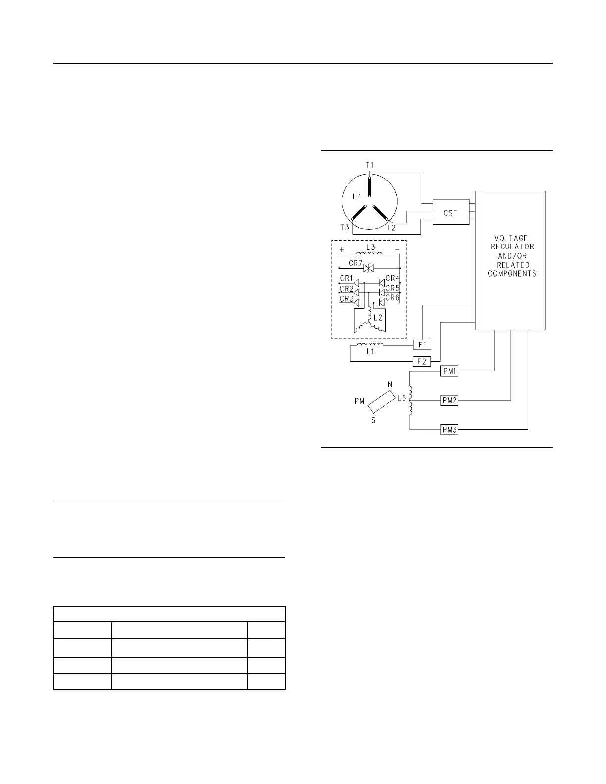
Illustration 114 g00669571
Generator Wiring Diagram
(CR1-CR6) Diodes
(CR7) Varistor
(L1) Exciter field (stator)
(L2) Exciter armature (rotor)
(L3) Main field (rotor)
(L4) Main armature (stator)
(L5) Pilot exciter armature
(PM) Permanent magnet
(RFA) Rotating field assembly
(CST) Customer supplied transformer
1. Make an external power source.
2. Refer to the above diagram. Disconnect “F1+” from
the voltage regulator. Disconnect “F2-” from the
voltage regulator. Disconnect the generator load.
Connect the generator output leads “T0” , “T1” ,
“T2” , and “T3” . Install the clamp-on ammeter to
generator output lead “T1” .
Note: When the line current is measured on multiple-
lead units, measure the current in each conductor per
phase. The currents can then be added.
SEBU7125-13
133
Maintenance Section
Generator - Dry
 Loading...